Rotel RX 820 820L OM

This is the 23 pages manual for Rotel RX 820 820L OM.
Read or download the pdf for free. If you want to contribute, please upload pdfs to audioservicemanuals.wetransfer.com.

Page: 1 / 23
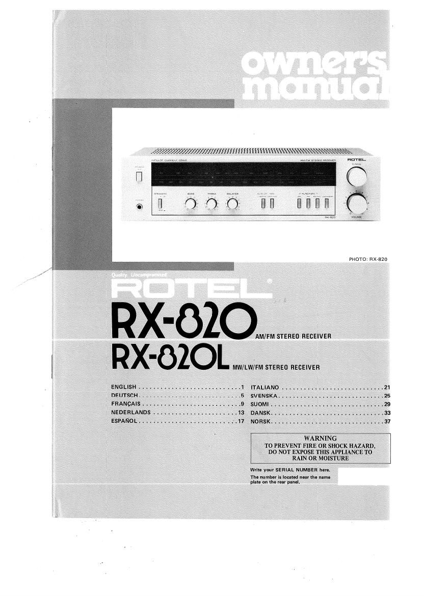
Rotel RX 820 820L OM

Extracted text from Rotel RX 820 820L OM (Ocr-read)


Page 1

LWhl-Iifi

PHOTO: R X-B2O

AM/FM STEREO RECEIVER
-OZOL MW/LW/FM STEREO RECEIVER

ENGLIsH ......................... '. . .1 ITALIANO ......................... . . .21
DEUTSCH SVENSKA ............... - .............. 2 5
FRANcAIs . .-. SUOMI . .. .. .29
, NEDERLANDS . . . DANSK. , , . . .33
ESPANOL. ......................... >.17 , 'NORSK ................ , .......... \. . . ._ .31

, WARNING

' TO PREVENT FIRE 0R SHOCK HAZARD,
~ DO NOT EXPOSE THIS APPLIANCE T0
RAIN 0R MOISTURE

Write your SERIAL NUMBER hen. -

Tho numbur is loam near ho name
platepn the rear panel. ~

Page 2

illllllSH

AM/FM STEREO RECEIVER RX-820
MW/LW/FM STEREO RECEIVER RX-820L

INTRODUCTION

We at Hotel want to thank you for purchasing
our audio product.

Rotel audio products are designed to use the
latest electronic technology, and they incorpo-
rate our long experience as a specialist manufac-
turer of audio equipment. We are confident
that you will find satisfaction in the high
quality sound and top performance, and that
you will find pleasure in the functional beauty
achieved through human-engineering concept.
Before starting operation, please read this
instruction manual thoroughly and acquaint
yourself with the proper mode of using the unit
and all its connections.

We hope you will enjoy top-notch performance
for many years to come.

BEFORE ENJOVMENT/
POWER SUPPLY

Follow the instructions below for maximum
safety:

1. Use a wall outlet for power supply

Be sure to connect the AC line cord directly to
a household wall outlet, and not to an auxiliary
outlet on another component. Be certain that
the outlet voltage matches the electrical rating
of the unit, found on the rear panel name plate.
2. Connecting and removing AC cord

Be sure to connect or disconnect the AC line
cord only after turning off the power switch to
prevent possible shock noise or damage to
the speakers.

3. Ventilate the unit well

Never block any ventilation holes at the top
and bottom of the unit. Be sure also to provide
ample ventilation space around the unit. Poor
ventilation may result in damage due to exces-
sive heat.

4. Do not open the cabinet

In order to avoid electric shock or damage to
the component, never open the cabinet. If a
foreign object falls inside the unit by mistake,
turn the power off, disconnect the wall plug,
and consult a qualified electrician or your
dealere

5. Installation

Be sure to place the unit in a level and flat place
where it is free from humidity, vibration, high
temperature and not exposed to direct sunlight.
Be careful not to place the unit in a highly
enclosed place such as near a wall or on a
bookshelf. A poor Ventilation will cause unde-
sirable effects to the unit.

6. Moving the unit

When transporting, remove the AC cord from
the wall outlet and all other connected cards on
the rear panel to prevent wire breakage and
short circuits.

1. If the unit gets wet

If the unit should get wet, immediately discon-
nect the AC cord, and consult your dealer or a
qualified electrician.

8. Cleaning and maintenance

Do not use chemicals such as benzine or thin-

ners on the front panel. Always use a soft, dry
cloth to clean the unit.

9. Owner's manual

Keep the owners manual near the unit, and
record the serial number (found on the rear
panel) on the cover.

EXCLUSIVE NOTE FOR U.K.

If your unit comes with a 2»core cable
without a plug, make certain live and
neutral leads are connected to the proper
terminals. Check that the terminals are
screwed down firmly and no loose strands
of wire are present.

IMPORTANT: The wires in this mains load
are coloured in accordance with the follow-

ing coda:
BLUE: NEUTRAL
BROWN: LIVE

As the colours of the wires in the mains lead
of this apparatus may not correspond with
the coloured markings identifying the
terminals in your plug proceed as follows.
The wire which is coloured BLUE Fnust be
connected to the terminal which is marked
with the letter N or coloured BLUE or
BLACK. The wire which is coloured
BROWN must be connected to the terminal
which is marked with the letter L or colour-
ed BROWN or RED.

SPEAKERS

The unit allows hookup of two speaker sys-
tems Use speaker systems with impedance
ratings of 4-16 ohms. Before hooking up your
speaker system, be sure to check its impedance,
which should be indicated either on the back of
the speaker, or in the speaker instruction man-
ual,

HOOKING UP SPEAKERS

0n the rear panel of the RX-820/L are two sets
of speaker terminals, "A and "B", to which
two speaker systems may be connected. Con-
nect the speaker leads of the right-hand speaker
to terminals R" of A" (or "3"), and the
speaker leads of the left-hand speaker to ter-
minals "L of "A" (or "8"). Make sure that the
"Jr" speaker lead is connected to the +" ter-
minal, and the "-" lead to the "--" terminal.
Strip 1.0cm (3/8") of the polyvinyl chloride
insulation from the end of each speaker lead.
Twist the exposed strands tightly, and secure
the end with a touch of soldier,

The terminals are the push-insert type, Insert
the end of the lead into the hole while pushing
on the button. Then release the button: the
hole will close and the cord is firmly fixed.
Note: When only one pair of speakers is used,
be sure to connect them to terminals "A". If
they are connected to terminals B", no sound
will be produced, even when the speaker
selector is set to A + B position,

AR AR:SPEAKER A/RIGHT AL

AL: SPEAKER A/LEFT
BR:SPEAKER B/RIGHT
BL : SPEAKER B/LEFT

SPEAKER A

E
eras

E
@LEB

Ba

SPEAKE R B

Page 6

SCHUTZKHEIS

Um das Gerfifi und die Laulsprecher var Be-
schédigung zu schiitzen, isi in dis Gerht em
Schuukreis eingebaut. Wenn die Lautspreoher
keinen Ton wiedergeben, kann dies an alner
durchgesohmolzenen Sicherung iisgen. Schalten
Sie dann das Geriét aus, ziehen Sie den Stacker
aus der Wandsteckdose, und wenden Sie sich an
|hren Hendler oder an einen qua|ifizierten

SPANNUNGSWAHL

Nicht mdglich bei Gerfiten iiir u.K., Kanada
und Skandinavien

Dieses Gerét kann auf 120V, 220V und 240V
umgestellt werden. |hr Geriit miiiite schon auf
die in Ihrer Gegend ubiicne Netzspannung
umgestellt sein. Sollten Sie aber in eine Gegefld
umziehen, in tier die Netzspannung andars ist,
dann kfinnen Sie das Gerfit Von lhren Fach-
héndler umstellen lassen,

HIANEAIS

AMPLl-TUNER STEREO MA/MF RX-820
AMPLl-TUNER STEREO PO/GOIMF RX-820L

CHER CLIENT,

rupture dun 1i] ou un Court-circuit,

BRANCHEMENT DES HAUT-

Fachmann.

TECHNISCHE DATEN
VERSTARKER-TEIL

Dauer-Ausgangsleistung ...... 20 Watt pro Kanal, mini RMS beide Kanfile

angasteuert an 8 Ohm von 20 bis 20.000 Hz
mit nicht mehr als 0,08% Gesamtklirrfakior.
27 Watt pro Kanal, (1 kHz, 4 Ohm,
Klirrfaktor1%)
lnsgesamt 70 Watt
Nicht mehr als 0,08% (DauevNennaus
gangsieistung)
Nicht mehr als 0,08% (1/2 Dauer-
Nennausgangsieistung)
Nicht mehr als 0,08% (1 Watt
Ausgangsleistung pro Kanal 8 Ohm)
.Nicht mahr als 0,08% (Dauerr
Nennausgangsleistung)
Nicht mehr 315 0.08% (1/2 Dauer»
Nennausgangsleistung)
Nichl mehr 9150,0896 (1 Wall
Ausgangs|eistung pro Kanal 8 Ohm)

DIN Ausgangsieistung .......

Musikleistung .
Klirrfaktor. ,
(20 bis 20.000 Hz)

lntermoduiationsverzerrung. . t
(60Hz:7kHz=4:1)

Ausgang: Lautspreoher ....... 416 Ohm
Koprnorer . . 1 .446 Ohm
Démpfungsfaktor. . . , . .30 (1 kHz, 80hm)

Eingangsempfindliohkeit/lmpedanz:
PHONO ............. 2,5 mV/47 kOhm
TAPE MONITOR ........ 150 mV/33 kOhm
Uberlastpegel (Klirrfaktor 0.5%, 1 kHz):
PHONO ........ . .90 mV
TAPE .3v


Frequenzgang
PHONO .
TAPE.

Klangregelung

2045.000 Hz, :0,3 013 (RIAA Entzerrung)
1048.000 HZ, +1,0 dB, >3,0 dB

:10 dB, 100 Hz

BASS ~ I 0 dB 10 kH
TREBLE ....... .11 , Z
Loudness. . . . ...... +7 dB (100 Hz), +4 dB (10 kHz)

(Laulsterkereglar euf r40 dB»S(e1|ung)
SignaLRauschabstand (IHF, A-NBIZWerk):

PHONO t . ....... 80 dB

TAPE MONITOR ........ 90 dB

UKW-TUNER-TEIL
Brauchbare Empfindnch keit
(Mono) .............. 10,8 dBf/1,9 uV
DIN Empfindlichkeit (Signal-Rauschabstand:
26 dB, 75 Ohm). t . , . .1.6 V
50 dB»Empfindlich keilsschwale:
Mono. . .17.2 dBf/4 1.1V
Stereo 140,7 1186/60 11V
Signalflauschabstand (bei 85 0150:
Mono ............ 70 dB
Stereo . 65 dB
Klirrfaktor (bei 65 dBf):
100 Hz. 1 ....... ,3% (Mono), 05% (Stereo)
1 kHz. . . ........ 0,13% (Mono), 0.5% (Stereo)
6 kHz. . . . ........ 0,35% (Mono), 0,6% (Stereo)
Frequenzgang . ........ 30 bis 14,000 H1, +0,3 dB, -3 dB
Einfangverhaltnis ....... 2,0 013
Nachbarkanalunlerd ckung
(1400 kHz) 1 . ...... 65 dB
Stdrunlerdrijckung ...... 70 dB
SpiegeifrequenZvDémpfung . . . .45 dB

75 dB
62 dB
i100 H211 kHz/10 kHz,

ZF-Dampiung. . . .
AM-Démpfung. . . ,

Stereotrennung t . . .
30 tie/33 dB/30'dB

Pilotton-Démpfungt . , . . 50 dB

SCA-Unterdriickung , . . .60 dB

. ,300 Ohm svmmetrisch,

Antennaneingang , . V . .
75 Ohm asvmmetnsch

AMvTUNER-TEIL MW LW (RX-820D
Empfindlichkeit ........... 300 uV/m 1.000 uV/m
Trennschérte ......... .32 dB

Signal-Rauschabstand ..... .45 on 45 dB

Spiegeirrequenz-Damprung .
ZF-Damprung .

......... Eingebaute Ferritantenne

Antenne . . ,
ALLGEMEINE DATEN

Spannungsversorgung ........ 220v150 Hz

Leistungsaufnahme . ....... 150 Watt

Gesamtabmessungen ........ B 430 mm x H 115 mm x D 332 mm
Nettogswicht . . ...... 5,81 kg

O Anderung der technischen Dalen vorbehalten!

ROTEL vous remercie de lachat de son appa-
reil audio. La technique do lélectronique
concue spécialement pour ies appareils HO-
TEL est I'une des pius avancées et nos expe-
riences trés approndies Ie prouvent: elies
nous classent comme les meilleurs fabriqnants
spécialistes des appareils audiot Nous somrnes
persuades que vous obtiendrez (Dute Ia satis-
faction que vous recherchiez par la haute
quallté du son at par ses performances die (out
premier ordre. Avant de brancher votre appa-
reil, lisel attentivemem le mode demploi er
vous saurez comment en titer le meilieur parti.
Nous espérons que Vous bénéficierez, des le
premier jour, d'une audition qui vous enchan-
tera et que vous renouvellerez touiours avec
un nouveau plaisir.

AVANT L'EMPLOI/ALIMENTATION

suivez Ies instructions ci-dessous pour un
empioi en mute securité de votre appareil.

1. Utilisez la prise murale pouralimenter votre

appareil.

AssureZ-Vous que Ie cordon secteur soit bien
raccordé e la prise murale. Assurez-vous que la
tension do sortie corresponde bien au régime
électrique indique sur le panneau arriere de
votre appareil.

2. Branchemant uu débranchement du cordon

CA

Branchez ou débranchez le cordon secteur CA
aprés evoir coupé le couranr pour éviter des
chocs aux hautsparleurs.

3. Assure: une bonne Ventilation

Ne jarnais bouchez ni obstruez les lrous de
ventilation sur les parties haute et basse de
lappareil, || faut aussi un espace suffisant
aulour de Iappareil. Une mauvaise ventilation
pourrait provoquer des dommages dds é une
chaleur excessivet

4. Ne dimomez pas l'appareil

Pour évitez tout choc électrique ou de dom-
mage aux composants, ne démontez pas len-
cadremenl de I'appareil. Au oz: of: un abjet é-
irenger serait tombe e Iintérieur de l'eppareil
par les trous de ventilation, coupez Ie courant
at débranchez Ie cordon secteur de la prise
murals, Duis (aims appe! é votre revendeur DU 21
un electrician qualifié.

5. Installation

Assurezvvous que Iendroit 00 vous allez instal»
ler l'appareil soit uniiormement plat, exempt
d'humidité, de vibrations, quil ne soit pas
sujet - des temperatures extremes et quil ne
soit pas exposé directement aux rayons du
soleil. Neccolez pas l'appareil comre le mur ou
dautre objet, car le manque de ventilation lui
en resulterait des dommages.
6. Transport d9 I'apparail

Lorsque vous transportez I'appareil, débranchez
le cordon secteur de la prise muraie ainsi que
mus les eutres raccordemems sur IE pans
neau arriére de l'appareil, vous éviterez ainsi la

7. Au on; oil l'eppareil aurait été expnsé i
l'humidité

Si votre appareil a été exposé a lhumidité,

débranchez immédiatement le cordon secteur at

faites appel évotre revendeur 0n é un elec-

tricien qualifié.

B. Nettoyage at antretien

N'utilisez pas de produits chimiques tels que

benzine ou diluant pour neuover le panneau

frontal de l'appareii, Utilisez touiours un

chiffon doux et sec pour nettoyer lappareil.

9. Cnnslrve! as manual d'instrnctions

Conservez ce manuel dinstructions prés de

l'appareil et inscrivez Ie numéro de série (sur le

penneau arriére) sur la couverture,

ENCEINTES

L'appareil peut recevoir deux svstéma dencein-
tes. Utiliser des enceintes dont Iimpédance soit
comprise entre 4 et 16 ohms, Avant de procé-
der au branchemem des enceintes, Vérifier leur
impedance, indiquée soit au dos des haut-par-
ieurs, soit sur |es instructions qui sy rapportent.

AR AR: HAUT-PARLEURS A/DROIT
AL: HAUT-PARLEURS A/GAUCHE
BR: HAUT-PAHLEURS B/DROIT
BL : HAUT-PARLEURS B/GAUCHE

PARLEURS

Le panneau arriére du RX»820/L comparte
deux ieux de borne: pour haut-parleurs, "A" at
"B", sur iesquels les haut-parleurs doivent étre
branches. Brancher les cébles du hauK-parleur de
droite sur les bornes "R de A" (ou "B"), et
les cébles du haunparleur de gauche sur les
bornes L" de A (Du "5). Prendre soin de
brancher Ie céble +" du haut-parleur snr IEI
borne 4", et la céble "-" sur la borne "-".
Dénuder sur environ 1cm is gaine des cables
de chacun des haut-parleurs afin de dégager les
conducteurs. Torsader fermement Ies fils et de-
poser une goutte de soudure pour solidifier I'ex-
trémité,

Les borne: sont du type £1 pousser pour insérer
les cébles. Insérer l'extrémité du cébie den-
ceinte tout en poussant sur ie plot de la borne.
Libérer le plot: le céble est alors serré.

Note: Lorsqu'une seule paire denceintes est
utilisée, effectuer le branchement sur les
homes A, Si IE branchement est opéré sur
195 homes "E", auoun son n'esl diffuse méme
si la sélecteur d'enceintes est réglé sur la posi-
tion A + B"

AL

SPEAKER A

_
E
9H6?

E
@Lea

an % BL
SPEAKER B