Rotel RX 600A OM
This is the 5 pages manual for Rotel RX 600A OM.
Read or download the pdf for free. If you want to contribute, please upload pdfs to audioservicemanuals.wetransfer.com.
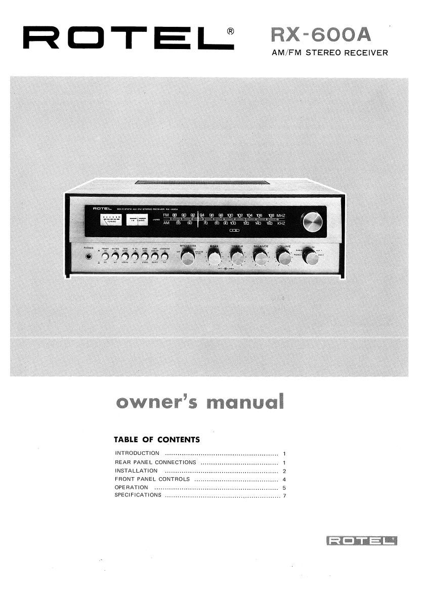
Extracted text from Rotel RX 600A OM (Ocr-read)
Page 1
R D T E U RX-SOOA
AM/FM STEREO RECEIVER
owners manuaI
TABLE OF CONTENTS
INTRODUCTION
REAR PANEL CONNECTIONS
INSTALLATION ................
FRONT PANEL CONTROLS ..
OPERATION
SPECIFICATIONS ,.
umbmad
Page 2
INTRODUCTION
We would like to take this opportunity to thank you for
purchasing our Stereo Receiver. With the high quality
design and workmanship that goes into making this
equipment, you can be assured of its flawless performance
for many years to come.
We have fitted every control and feature you could
conceivably need. Designed for both versatility and ease
of operation, this piece of equipment will add professional
studio fleIibility to your Hi»Fi sound center. The per-
formance Iis exceptional; it will allow you to experience
true high fidelity as never before. Its full and natural
stereophonic reproduction offers you musical entertain-
ment approaching that of live performances. We sin-
cerely hope you will treasure this professional equipment.
In order to obtain the maximum use out of your unit,
Please read the following pages of this Owners Manual
carefully.
Do not attempt to operate the unit until you have made
all the necessary connections.
REAR PANEL CONNECTIONS
'EREO RECORD PLAYER STEREO RECORD PLAYER
(with mag cartridge) (with cera cartridge)
STEREO TAPE RECORDER STEREO TAPE RECORDER
(with monitor head)
Cl
0 O
Cl
O O
flop poo poo flop
p0 o0 so me
Q 00A.
0 0 GOO GOO
AM FERRITE
BAR ANTENNA
8-TRACK
PLAYER
OUTPUT INPUT OUTPUT lNP T
Q ,QU
{IO/EEG
1920190
Cl
0 O
TEREO RECORD PLAYER
(with mag cartridge)
5M ANTENNA 3009 BALANCED
L__
3M ANTENNA 759 UNBALANCED
AM ANTENNA
LEFT SPEAKERS
DC FUSE (R CHAN) 3A
DC FUSE (L CHAN) 3A
AC FUSE 3A, 100 & 117V -
+ - + - +
O O O O O O O O
SPKR-l SPKR-2 SPKR-1 SPKR-Z
RIGHT SPEAKERS
AC POWER INPUT
C OUTLETS (SWITCHED)
MAX 150 WATTS
1.5A, 220 & 240V
INSTALLATION
IMPORTANT: Do not apply power to this unit without
first making sure that speakers are connected properly and
all the other necessary connections are made.
AM ANTENNA CONNECTION
No external antenna will generally be required for AM,
since a ferrite loopstick antenna is supplied at the rear of
the receiver. For best reception, extend the loopstick fully
out from the receiver chassis.
If you live in a difficult reception area, the use of an
external wire antenna may be desirable. Connect the
antenna lead to the terminal marked AM on the rear
panel. The wire antenna should be as long as possible, and
oriented for best reception. It must be kept away from
large metal objects, power lines or electrical machinery to
insure reception without extraneous noise.
FM ANTENNA CONNECTION
Owing to the high sensitivity of the FM tuner section of
the receiver, the wire antenna supplied is sufficient for
most locations. Connect this to either FM antenna
terminal marked 300 ohms, and mount horizontally, for
instance by tacking to the shelf on which the receiver is
mounted. In difficult reception areas, the use of an
outdoor antenna may prove necessary. Follow its instruc~
tions for proper connection. 300 ohm balanced and 75
ohm unbalanced terminals are supplied. When using an
external antenna, connect both leads of the antenna to
the two 300 ohm FM antenna terminal posts on the rear
chassis. When using a 75 ohm unbalanced coaxial cable
for antenna, connect between 75 ohm and G terminal
posts with the outer conductor or shield of the cable
connected to the G terminal.
SPEAKER CONNECTION
This unit is equipped with terminals for connecting two
sets of speakers. Connect your main pair of speakers to
the terminals marked SPKR-l. Ensure that your right
speaker is connected to the SPKR-l terminal marked
+, and that the ground i--) terminal on the right
speaker is connected to the terminal marked "-" on the
extreme right of the terminal block. Similarly, connect
your left speaker between the adjacent SPKR~1 terminals
marked + and -.
If you wish to connect a second pair of speakers, connect
them to SPKR-2 terminals in the manner described above.
Caution: Ensure that the speaker leads are fastened
securely to the proper terminals, and that there are no
stray strands which may cause shorting between terminals.
If 2 sets of speakers are played simultaneously, the
impedance of each unit should not be less than 6 ohms.
PHASING:
When all connections have been made, and the unit is
operating, a check on correct speaker phasing should be
made. This is described in a later section.
RECORD PLAYER CONNECTION
The shielded cables from your stereo record player should
be terminated with RCA type phono plugs. To avoid loss
in the high frequencies, the cables should not exceed 10
feet (3 m) in length.
This unit is equipped with terminals for connecting up to
three record players. If your record player has a magnetic
cartridge, connect its left and right leads to the corre-
sponding LEFT and RIGHT terminals marked PHONO 1,
and if you have another record player with a magnetic
cartridge, connect its leads to the PHONO 2 terminals
marked MAG. If your record player has a ceramic or
crystal cartridge, connect its leads to the PHONO 2
terminals marked CERA.
If your record player has a ground cable emerging besides
two input cables, connect this ground cable to the ground
terminal post marked GND on the rear chassis.
TAPE RECORDER CONNECTION
Terminals are supplied for connecting two tape recorders
(which incorporate playback preamplifier). For a recorder
with a separate playback head (i.e. Monitor facilities),
connect its right and left output cables to the TAPE
terminals marked MONITOR, and connect its right and
left input cables to the TAPE terminals market OUT. If
you have another tape recorder or one without the
monitor head, connect its input leads to the terminals
marked REC/OUT, and connect its output leads to the
terminals marked AUXZ. If you wish to connect a tape
recorder, 8 track cartridge player, cassette, TV sound or a
ceramic microphone for playback purpose only, connect
its output leads to the terminals marked AUXl.
PRE AMP OUT AND MAIN AMP IN RECEPTACLES
There are pairs of terminals marked PRE AMP OUT and
MAIN AMP IN, connected with a pair of jumper pins on
the rear chassis. Normally with the pins in place, your
receiver is the combined equipment of integrated pre-
amplifier and main-amplifier sections. However, by re-
moving the jumper pins, your unit in essence becomes two
independent components consisting of one pre-amplifier
and one main-amplifier.
These receptacles are intended for use with any necessary
equipment designed to be installed between the pre-
amplifier and the main-amplifier or for separate use of
either section alone. Such equipment as electronic audio
equalizer or reverberation unit can be used; or, another
preamplifier or main-amplifier may be hooked up. Simply