Rotel RX 152 OM

This is the 7 pages manual for Rotel RX 152 OM.
Read or download the pdf for free. If you want to contribute, please upload pdfs to audioservicemanuals.wetransfer.com.

Page: 1 / 7
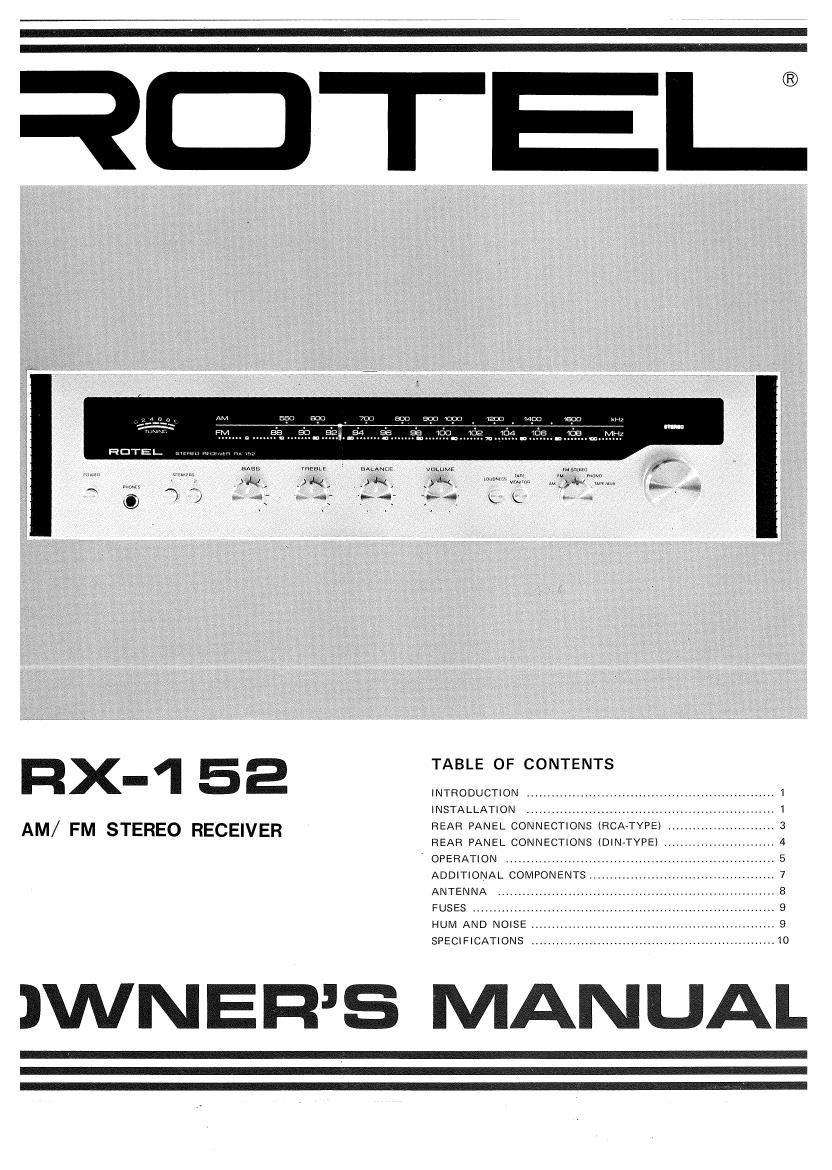
Rotel RX 152 OM

Extracted text from Rotel RX 152 OM (Ocr-read)


Page 1

mm . '51::
1:34 is fie
n~ . .

HOTEL. nymmmmw

meme 1 mum: w push
_ g: ,>

f: . m, M gm
W 1 14: K K

«bums

FIX 1 52 W
-
INTRODUCTION I 1

INSTALLATION ...................................................... I
AM/ FM STEREO RECEIVER REAR PANEL CONNECTIONS (RCAATYPE) .......................... 3
REAR PANEL CONNECTIONS (DIN-TYPE) ........................... 4
OPERATION ................................................................. 5
ADDITIONAL COMPONENTS.
ANTENNA ................................................................... 8
FUSES ........................................................................ 9
HUM AND NOISE .......................................................... 9
SPECIFICATIONS .......................................................... 10

JWNERS MANUAL

Page 2

INTRODUCTION

We would like to take this opportunity to thank you for
purchasing our audio component. With the high quality
design and workmanship that goes into making this
equipment, you can be assured of its flawless performance
for many years to come.

We have fitted every control and feature you could

conceivably need. Built for both versatility and ease of 7

operation, this piece of equipment will add professional
studio flexibility to your Hi»Fi sound center. The per-
formance is exceptional; it will allow you to experience
true high fidelity as never before. Its full and natural

sound reproduction offers you musical entertainment
approaching that of live performances. We sincerely hope
you will treasure this professionaltype component.

The operations are really simple if you read at least the
first two sections of this manual. The third section covers
additional components such as a record player and a tape
recorder that can be connected to this equipment, and is
recommended to be followed if you wish to realize the
full potential of this advanced and superbly engineered
equipment.

INSTALLATION

Caution: Do not apply power to the equipment without
first making sure that speakers are connected properly and
that the units VOLUME is set to minimum.

LOCATING THE UNIT

Although the unit normally does not develope high heat,
it should be placed in such a way that its ventilation
system will not be impeded. Place the unit on a hard
surface ~ any conveniently located shelf or table where
not affected by heat. Leave at least 2 inches (5 cm)
clearance on each side and in the rear of the unit, and
about 3 inches (8 cm) above the unit. Never directly place
an object on the ventilation at the top of the unit, if there
is such a ventilation.

LOCATING SPEAKERS

Caution: Check that each speakers rated impedance is 8
ohms or higher, (The value should be marked near its
connecting terminals or indicated in its instruction book
or, if not, consult your dealer.) If any speaker is rated at 4
ohms, and if you have four speakers, severe overload and
distortion may be incurred when all four speakers are
played simultaneously. In the event you have speakers
rated at 4 ohms, make sure that only two 'speakers are
played at a time.

A. STEREO OPERATION

1. MAIN SPEAKERS - Two speakers are required for
stereo operation. Place both speakers against a wall or
on a shelf so that they face your selected listening
position and are equal distance from you. For
optimum stereo effect, they should be 10 to 15 feet (3
meters) apart and, if possible, at about ear level height.

You may determine best locations to suit your
personal tastes and listening conditions.

2. REMOTE SPEAKERS r If you wish to enjoy stereo
sound in another room in your home, you can connect
a pair of speakers to the SPEAKER 2 terminals located
on the unit's rear panel. Though you will need long
cables between the unit and the speakers in another
room, make sure they are not longer than 50 to 60 feet
(15 to 20 meters) in length and that they are of heavy
duty type in order to prevent loss of volume.

Follow the procedure described above in the item (1) for

placing the remote speakers.

B. SIMULATED 4-CHANNEL OPERATION
Four speakers are required to be set in one room for this
simulated 4-channel operation made possible by use of a
special speaker matrix circuit and an activation switch on
the units rear panel.

Place a pair of speakers connected to SPEAKER 1
terminals in the same manner as described above in the
item (1) of STEREO OPERATION section. They will be
referred to as the FRONT speakers.

Placement of the speakers connected to SPEAKER 2
terminals (referred to as the BACK speakers) will vary
with your room size, seating arrangement and acoustic
conditions. If possible, provide allowance on the length of
cables as later on you may wish to locate the speakers
differently from the original positions. We have suggested
a common way of placing the BACK speakers as
illustrated in Fig. l, but you may arrange them in any way
to suit your tastes and listening conditions. Try some
experimentations to locate optimum positions for best
sound dispersion and ambience.

FRONT
SPEAKERS

LISTENER

BACK SPEAKERS

Fig. 1 Suggested speaker location for 4-clmnnel operation.

SPEAKER CONNECTION
Caution: Do not apply power to the unit until the
speakers are connected properly as described below.

A. If your unit has screw and RCA-type speaker terminals.
When connecting the speakers to the SPKR 1 screw
terminals, make sure that the bare wires at the ends of
each cable do not touch each other or adjacent terminals.
Connect one lead of each speaker cable to its correspond-
ing terminal and another end to the adjacent terminal; the
positive (+) lead of the speaker is connected to the (+)
screw terminal and the ground (-) lead to the (-) screw
terminal. (Note: if necessary, after stripping each end of
speaker leads to obtain a bare wire, twist the bare strands
together so it will be easy to wrap around each screw
terminal and also prevent shorting among stray strands.)
When connecting the speakers to the SPKR 2 terminals,
make sure that each end of cables has a RCA-type pin
plug. Connect each lead to the corresponding RCA-type
jack, right to RIGHT and left to LEFT.

B. If your unit has DIN-type speaker terminals.

When connecting the speakers to the DIN-type terminals,
make sure that the speaker cables have DIN-type 2»prong
plug on their ends. Simply plug these cables to the
corresponding SPKR 1 terminals, right to RIGHT and left
to LEFT,

If you have another pair of speakers, connect to the SPKR
2 terminals in the same manner as the above.

See Fig. 2 and Fig. 3.

AM ANTENNA CONNECTION

A ferrite-core AM loopstick antenna is affixed inside the
unit for optimum reception.

If you live in a difficult reception area and the AM
loopstick does not give sufficient reception, an external
antenna may be required. There is a terminal on the rear
panel for such antenna connection, so refer to the
ANTENNAS section of this manual for installing external
antenna.

FM ANTENNA CONNECTION

Due to the high sensitivity of the FM tuner section of the
unit, a T"-shape dipole antenna (or sometimes even a
48inch long single wire) is sufficient for most locations.
Connect this to both FM antenna terminals marked 300
ohms and fasten the short arms of the antenna horizontal-
ly to a non-metallic surface, for instance by tacking to the
shelf on which the unit is mounted or to the wall where
reception is optimum.

In extremely difficult reception areas, an outdoor antenna
may prove necessary, Refer to the ANTENNAS section of
this manual for installing outdoor antennas.

COMPONENTS CONNECTIONS

This unit is designed to handle a record player either with
magnetic or ceramic cartridge, a stereo tape recorder and
an additional auxiliary component such as stereo cassette
or 8»track cartridge deck.

We recommend that you familiarize yourself with basic
operations before connecting any such units. Refer to the
ADDlTlONAL COMPONENTS section provided in this
manual for connections and operations of these com»
ponents.

AC OUTLET

The outlet marked SWITCH ED on the rear panel provides
power and switching control to whatever component you
may wish to connect to the unit. For example, if you
connect the power cord of your record player to the
outlet, the record player will be activated and deactivated
by the power switch on the unit.

Caution: Do not connect components whose total power
consumption exceeds 200 W.

POWER SUPPLY CONNECTION

For power the unit requires the normal house AC
electrical current.

Before connecting up ensure that the unit has a suitable
plug fitted. If you need to fit a plug, ensure live, neutral
and (where appropriate) earth leads are connected to the
proper terminals. In some cases there is an instruction to
fit a plug attached to the power cord, so follow the
instruction before fitting the plug,

If in any doubt about connecting to the power source,
consult a qualified electrician.