Rotel RT 724 OM
This is the 5 pages manual for Rotel RT 724 OM.
Read or download the pdf for free. If you want to contribute, please upload pdfs to audioservicemanuals.wetransfer.com.
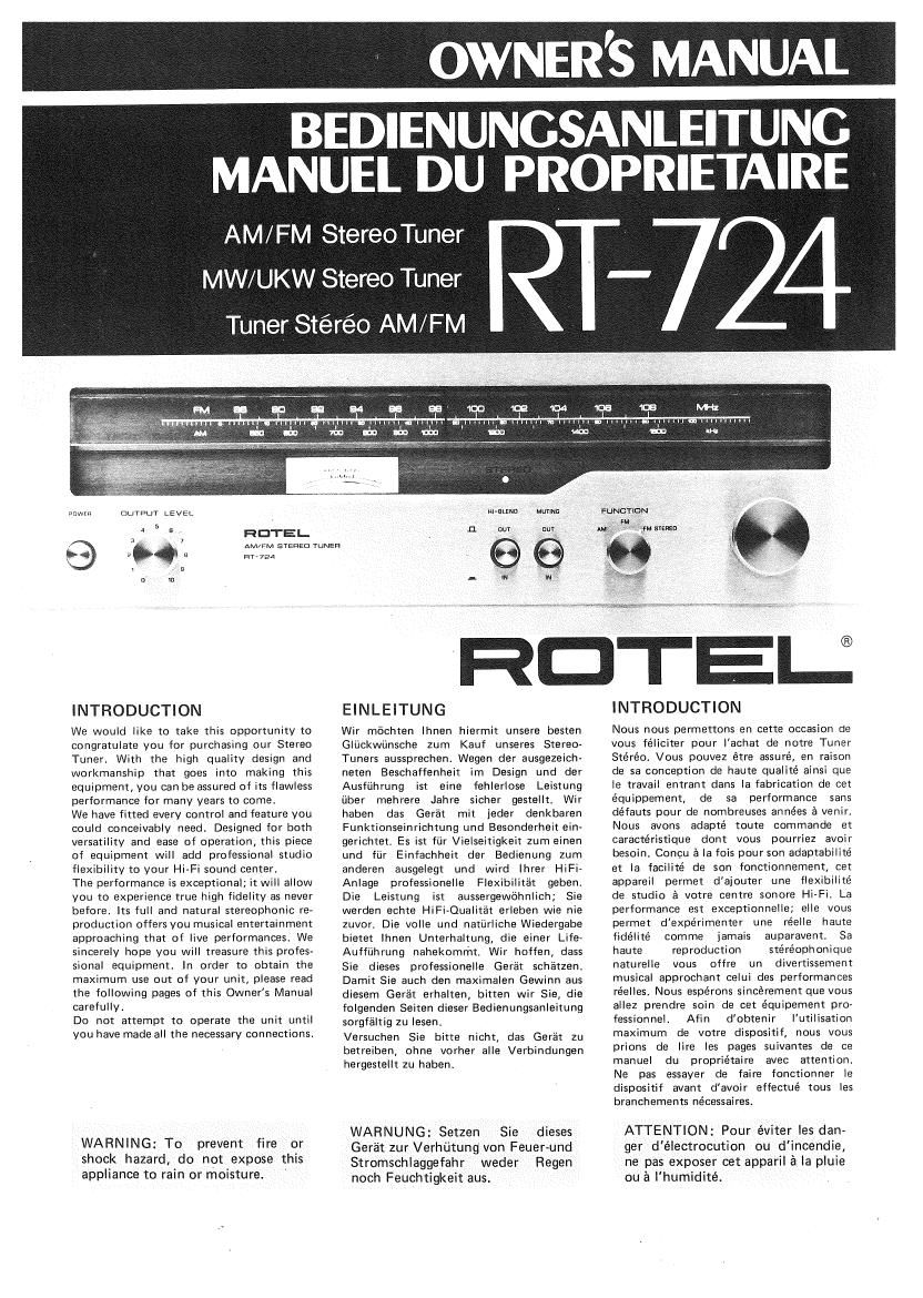
Extracted text from Rotel RT 724 OM (Ocr-read)
Page 1
OWNER'S MANUAL
BEDIENUNGSANLEITUNG
MANUEL DU PROPRIETAIRE
AM/FM Stereo Tuner
MW/UKW Stereo Tuner
Tuner Stéréo AM/ F M
143er Burnt. LEVEL
HOTEL
tar-724
INTRODUCTION
We would like to take this opportunity to
congratulate you for purchasing our Stereo
Tuner. With the high quality design and
workmanship that goes into making this
equipment, you can be assured of its flawless
performance for many years to come.
We have fitted every control and feature you
could conceivably need. Designed for both
versatility and ease of operation, this piece
of equipment will add professional studio
flexibility to your Hi»Fi sound center.
The performance is exceptional; it will allow
you to experience true high fidelity as never
before, Its full and natural stereophonic re-
production offers you musical entertainment
approaching that of live performances We
sincerely hope you will treasure this profes-
sional equipment. In order to obtain the
maximum use out of your unit, please read
the following pages of this Owners Manual
carefully.
Do not attempt to operate the unit until
you have made all the necessary connections.
WARNING: To prevent fire or
shock hazard, do not expose this
appliance to rain or moisture.
AM/FM s'rEfiEu runs»:
nl-SLElfl Munro
:1 uuv pm
g in m'
We
FuNm-iaN
svmn
DTEIJ
EINLEITUNG
Wir mochten Ihnen hiermit unsere hasten
Glijckwiinsche Zum Kauf unseres Stereo-
Tuners aussprechen. Wegen der ausgezeich-
neten Beschaffenheit im Design und der
Ausfiihrung ist eine fehlerlose Leistung
iiber mehrere Jahre sicher gestellt. Wir
haben das Gerat mit ieder denkbaren
Funktionseinrichtung und Besonderheit ein-
gerichtet. Es ist fiir Vielseitigkeit zum einen
und fLir Einfachheit der Bedienung zum
anderen ausgelegt und wird lhrer HiFi-
Anlage professionalle Flexibilitat geben.
Die Leistung ist aussergewohnlich; Sie
werden echte HiFi-Qualitat erleben wie nie
zuvor, Die volle und natiirliche Wiedergabe
bietet lhnen Unterhaltung, die einer Life~
Auffiihrung nahekommt. Wir hoffen, dass
Sie dieses professionelle Gerat schatzen.
Damit Sie auch den maximalen Gewinn aus
diesem Gera't erhalten, bitten wir Sie, die
folgenden Seiten dieser Bedienungsanleitung
sorgfaltig zu lesen.
Versuchen Sie bitte nicht, das Gerat zu
betreiben, ohne vorher alle Verbindungen
hergestellt zu haben.
WARNUNG: Setzen Sie dieses
Get-"at zur Verhfltung von Feuer-und
Stromschlaggefahr weder Regen
noch Feuchtigkeit aus.
INTRODUCTION
Nous nous permettons en cette occasion de
vous féliciter pour Iachat de notre Tuner
Steréo. Vous pouvez étre assure, en raison
de sa conception de haute qualite ainsi que
le travail entrant dans la fabrication de cet
équippement, de sa performance sans
defauts pour de nombreuses années a venir.
Nous avons adapté toute commande et
caractéristique dont vous pourriez avoir
besoin. Concu a la fois pour son adaptabilite
et la facilité de son fonctionnement, cet
appareil permet daiouter une flexibilité
de studio 5 votre centre sonore Hi»Fi. La
performance est exceptionnelle; elle vous
permet d'expérimenter une réelle haute
fidélité comme jamais auparavent, Sa
haute reproduction stéréophonique
naturelle vous offre un divertissement
musical approchant celui des performances
réelles. Nous espérons sincérement que vous
allez prendre soin de cet équipement pro»
fessionnel. Afin d'obtenir l'utilisation
maximum de votre dispositif, nous vous
prions de lire les pages suivantes de ce
manuel du propriétaire avec attention.
Ne pas essayer de faire fonctionner Ie
dispositif avant d'avoir effectué tous les
branchemenm nécessaires.
ATTENTION: Pour éviter les dan-
ger d'électrocution ou d'incendie,
ne pas exposer cet apparil a la pluie
ou a lhumidité.
Page 2
OUTDOOR FM ANTENNA 759
UKW (FM) Aussenantenne 75ft
ANTENNE FM EXTERIEURE 75R
INDOOR FM ANTENNA 3009
UKW (FM) Innenantenne 3009
ANTENNE FM INTERIEURE DE 3009
L
r-\
OUTDOOR AM ANTENNA 759 COAXIAL
MW (AM) Aussenantenne ANTENNA ADAPTER
ANTENNE AM SOCKET
EXTERIEURE 753 Koaxialantenne/
AM FERRITE BAR ANTENNA
MW (AM) Ferritantenne
ANTENNE A FERRITE AM
i . I swam :l KIM mm on Any stews moi LlRfiFlfl} m comvww
g WM my: cm; In WADflfD Kmllll Fcc suits, Pm l5, susemc
Adapterbuchse
PRISE D'ADAPTEUR
D'ANTENNE DE
COAXIAL DE 75.0I
r1.
.v ..
OUTDOOR FM
ANTENNA 3009 .
UKW (FM) Aussenan-
tenne 3009
ANTENNE FM
EXTERIEURE 30052
sum in:
AC POWER CORD
FM
GROUND-
Erde
PRISE DE TERRE
O
0 099999 00900
future)
STEREO INTEGRATEDAMPLIFIER
lntegrierter Stereoverstarker
AMPLIFICATEUR INTEGRE STEREO
DETECTOR OUTPUT
(Use to accept an adapter
to enable receive 4-channel
4»channel broadcasting
whenever effected in the
Netzstecker
CORDON D'ALIMENTATION
DE COUR. ALT.
UKW~ Demodu-
Iator-AusganglAn-
schluss aines Adapters,
urn eventuell zukiinftige
4-Kanalsendungen zu
empfangen)
o o o o O
' I
SORTIE DE DETECTEUR
(Utilisation permettant de recevoir de diffisions
sur le canal-4 quelque soit la date dappllcation
ultérieure)
.3
INSTALLATION
IMPORTANT: Do not apply power to this
unit without first making sure that all the
necessary connections are properly made.
AM ANTENNA CONNECTION
No external antenna will generally be re-
quired for AM. since a ferrite loopstick
antenna is supplied at the rear of the unit.
For best possible reception, extend the loop-
stick fully away from the tuner chassis.
If you live in a difficult reception area, the
use of an external or outdoor antenna may
be desirable. Connect a single wire antenna
lead to the terminal marked AM on the rear
chassis. The wire antenna should be as long
as possible, and oriented for best reception.
It must be kept away from large metal ob-
jects, power lines or electrical machinery to
insure reception without extraneous noise.
FM ANTENNA CONNECTION
Owing to the high sensitivity of the FM tuner
section of the unit, the antennawire supplied,
is sufficient for most locations.
Connect this to both FM antenna terminals
marked 3000hms, and mount horizontally,
for instance by tacking to the shelf on which
the receiver is mounted. In difficult reception
areas, the use of an outdoor antenna may
prove necessary. Follow its instructions for
proper connection.
When using a 75 ohm unbalanced coaxial
cable for antenna, you may connect between
75 ohm and G terminal posts with the outer
conductor or shield of the cable connected
to the G terminal or use an adapter holder
and plug into the 75 ohm adapter socket.
Follow instruction on coaxial cable on fur-
ther details.
GROUND
Although it is not necessary to do so, but if
you wish to ground the tuner, connect a wire
from the terminal designated GND on the
rear chassis to the ground terminal on your
amplifier or to a nail driven into the earth.
VARIABLE (Output Level Control)
AND NON-VARIABLE OUTPUTS
There are two pairs of output jacks designatv
ed LEFT and RIGHT on the rear chassis.
The left hand pair is a standard, nonvariable
output for use with most standard amplifiers.
These pair of output should be connected to
the corresponding left and right input
(TUNER or AUX) jacks on your amplifier.
For your convenience, the connecting cables
for this purpose are supplied with this unit.
The right hand pair is a variable output of
which output level can be varied from 0 to
0.3V (30%, 4OOHZ) for AM and from 0 to
1.5V (100%, 400Hz) for FMwith the output
level control on the front panel. This output
is for use with amplifiers whose input level
requirements are different from the standard
amplifiers. The control as its left most posi-
tion is 0 output. Turning it to the right will
increase the output level proportionately. and
at its right most position, the output level
will be at maximum.
To achieve appropriate output level for your
amplifier's input requirement,set the control
lNBETRlEBNAHME
WlCHTlG: Versichern Sie sich vor lnbetrieb-
nahme des Gerates, class alle Anschliisse
richtig hergestellt sind.
MW (AM) - ANTENNENANSCHLUSS
Normalerwelse wird keine Aussenantenne
fiir MW-Empfang benétigt, da sich an der
Riickseite des Gerates eine Ferritantenne
befindet. Um besten Empfang zu gewahr-
Ieisten, bringen Sie die Ferritantenne in die
weiteste Position vom Tuner-Chassis. Falls
Sie in einer empfangsungiinstigen Gvegend
wohnen, ware eine externe bzw, Aussen-
antenne wiinschenswert. Verbinden Sie das
Ende einer einfachen Drahtantenne mit dem
Anschluss, der mlt AM an der Riickseite des
Chassis gekennzeichnet ist. Die Drahtantenne
sollte so Iang wie méglich und fiir besten
Empfang ausgerichtet sein. Sie muss yon
grossen Metallteilen, Netzkabeln bzw. elek-
trischen Geratan ferngehalten werden, um
Empfang ohne Storgerausche zu gewahr-
leisten.
UKWIFM)-ANTENNENANSCH LUSS
lnfolge cler hohen Empfindlichkeit des
UKW-Tuner-Teils des Geria'tes geniigt fiir die
meisten Ortslagen die gelieferte Antenne.
Verbinden Sie die Antenne mil beiden
UKW-Antennenanschliissen, die mit 300
Ohm gekennzeichnet sind, und bringen Sie
sie horizontal an, in dem Sie die Antenne
zum Beispiel am Regal befestigen, auf dem
der Empfanger aufgebaut ist. In schwierigen
Empfangslagen mag eine Aussenantenne
notwendig sein. Bitte befolgen Sie die
folgenden Anweisungen fijr richtige Ver~
bindung.
Falls Sie ein 75-Ohm unsymmetrisches
Koaxkabel Verwenden, verbinden Sie
zwischen 75-0hm und "G" Anschliisse,
wobei der a'ussere Leiter bzw. die Abschir-
mung des Kabels mit dem "G" Anschluss
verbunden wird. Sie konnen auch einen
Zwischenstecker benutzen und in die
75 Ohm Adapterbuchse stecken. Befolgen
Sie die folgenden Anweisungen fiir den
Gebrauch von Koaxkabel.
ERDE
Es ist zwar nicht notig den Tuner zu erden,
aber wenn Sie es wiinschen, verbinden Sie
einen Draht vom Ausgang GND an der
Riickwand des Chassis mit dem Erdanschluss
lhres Verstarkers oder mit einem Erdungs-
stab, den Sie in die Erde treiben.
VARIABLE (AUSGANGSPEGEL-
KONTROLLE)
UND NIGHT-VARIABLE
AUSGANGE
Es gibt zwei Paar Ausgangsbuchen -- gekenn-
zeichnet mit LEFT und RIGHT - an der
Riickwand des Chassis. Das linke Paar ist
ein nicht-variabler Ausgang fijr die meisten
normalen Verstéirker. Disses Paar sollte mit
den entsprechenden linken und rechten
(TUNER oder AUX) Eingangsbuchsen lhres
Verstarkers verbunden werden. Die Ver-
bindungskabel fiir diesen Zweck werden
dem Gerat mitgeliefert.
3
INSTALLATION
INPORTANT: Ne pas brancher ce dis-
positif sur le courant sans s'assuger
auparayant que les branchements nécessaires
sont effectués proprement.
BRANCHEMENT DE L'ANTENNE
AM
L'AM ne demande généralement aucune
antenne externe, une tige bouclée a
ferrite étant pourvue s l'arriere du dispositif.
Pour une reception optimum étendre
totalement la tige bouclée en dehors du
chassis du tuner. Si vous yivez dans une zone
a reception difficile, il peut étre préférable
dutiliser une antenne exterieure. Brancher
une antenne a fil unique au terminal marqué
AM sur l'arriere du chassis. Lantenne en fil
doit étre aussi Iongue que possible, at
oriente'e pour la meilleure reception. Elle
doit étre maintenue hors des objets metal-
quues de grande dimension, les Iignes de
tension ou tout materiel électrique, afin de
permettre une reception sans parasite.
BRANCHEMENT DE LANTENNE
FM
DO 2) la grande sensibilité de la section du
tuner FM du dispositif, Ie fil d'antenne
fourni est suffisant pour la plupart des
emplacements. Le brancher a la fois aux
bornes d'antenne FM marquees 300 ohms,
et la monter horizintalement en la clouant
sur l'étagére sur laquelle est monté le
récepteur. Dans les zones de reception
difficile, il est parfois nécessaire d'utiliser
une antenne extérieure. Pour effectuer un
branchement adéquat nous vous prions de
suivre attentivement les instructions.
En cas d'utilisation d'un cable de coaxial
non compensé de 75 ohms pour antenne,
vous ayez la possibilité de brancher entre les
bornes et les 75 ohms avec le conducteur
exterieur ou la protecteur du cable branché
a la borne G, ou dutiliser un support
d'adapteur et de le brancher dans la prise
d'adapteur de 75!). Suivre les instructions
traitant du cable de coaxial en cas de besoin
de details supplémentaires.
PRISE DE TERRE
Bien que cela ne soit pas necessaire, mais
en cas de désir de mettre le tuner a la masse.
brancher le fil a partir de la borne GND
située sur le chassis arriere a la borne de
prise de terra, sur votre amplificateur, ou
a un clou s'enfoncant dans la terre.
SORTIES VARIABLES ET FIXES
(Controle de niveau de sortie)
II existe deux paires de iacks de sortie
gauche et droit "LEFT "RIGHT" sur le
chassis arriere.
La paire située a gauche est une sortie fixe
standard utilisable avec la plupart des
amplificateurs standards. Oette paire de
sorties doit etre branchée respectivement
aux jacks de sortie de droite et de gauche
(TUNER ou AUX) de votre amplificateur.
Pour Votre conveniance, les cables de