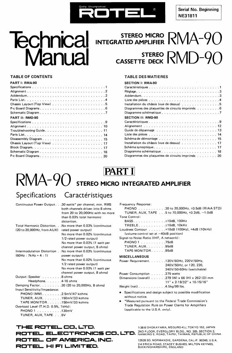
Rotel RMA 90 Service Manual
This is the 20 pages manual for Rotel RMA 90 Service Manual.
Read or download the pdf for free. If you want to contribute, please upload pdfs to audioservicemanuals.wetransfer.com.
Extracted text from Rotel RMA 90 Service Manual (Ocr-read)
Page 1
Technical
Manual
TABLE OF CONTENTS
PART I: RMA-eo
STEREO MICRO
INTEGRATED AMPLIFIER
CASSETTE DECK
Serial No. Beginning
NE31811
RMA-9O
RMD-QO
TABLE DES MATIERES
SECTION I: EMA-90
STEREO
Specifications ............................. 1 Caractéristiques ............................ 1
Alignment ............................... 2 Fiéglage .............................. 3
Addendum ............................... 2 Addendum ............................... 3
Parts List. . , .......................... .4 Liste des pieces ............................ 4
Chassis Layout (Top View) .................. .5 Installation du chassis (vue de dessus) ............... 5
P-c Board Diagrams .......................... 6 Diagrammes des plaquettes de circuits imprimés ......... 6
Schematic Diagram .......................... 7 Diagramme schematique ....................... 7
PART II: RMD«90 SECTION II: RMDBO
Specifications ............................. 9 Caractéristiques ............................ 9
Alignment .............................. 1O Alignement ............................. 12
Troubleshooting Guide ....................... 11 Guide de dépannage ........................ 13
Parts List .............................. 14 Liste des piéces ........................... 14
Disassembly Diagram ........................ 15 SChémfl d5 démontage ----------------------- 15
Chassis Layout (Top View) , , ________________ 17 Installation du chassis [vue de dessus) .............. 17
Block Diagram .......................... 17 Schéma svnoptique ................
Schematic Diagram ............... 18 Diagramme schematique .....
P4; Board Diagrams ............... 20 Diagrammes des plaquettes de circurts imprimes ........ 20
RM/ \ 90 STEREO MICRO INTEGRATED AMPLIFIER
SpeCIfIcatIons Caracteristiques
Continuous Power Output. . .30 watts" per channel, min. RMS Frequency ReSPDVSBi
both channels driven into 8 ohms PHONO ........... 30 to 20,000H2, t0.5dB (RIAA STD)
from 20 to 20,000H2 with no more
than 0.03% total harmonic
distortion.
.No more than 0.03% (continuous
rated power output)
No more than 0.02% (continuous
1/2 rated power output)
No more than 0.03% (1 watt per
channel power output, 8 ohms)
.No more than 0.03% (continuous
power output)
No more than 0.02% (continuous
1/2 rated power output)
No more than 0.03% (1 watt per
channel power output, 8 ohms)
Output: Speaker ........ 8 ohms
Headphone. . . . 4-16 ohms
Damping Factor ...... 30 (20 to 20,000Hz, 8 ohms)
Input Sensitivity/Impedance
Total Harmonic Distortion. .
(20w 20,000Hz. from AUX)
Intermodulation Distortion .
(60H2 : 7kHz = 4 : 1)
PHONO (MM) ..... 5mV/47 kohms
TUNER, AUX ..... 150mV/33 kohms
TAPE MONITOR ...... 150mV/33 kohms
Overload Level (T.H.D. 0.5%, 1kHz):
PHONO 1 .......... 130mV
TUNER, AUX, TAPE . . .5V
THE HOTEL CO" LTD.
HOTEL ELECTRONICS CO" LTD.
HOTEL OF AMERICA. INC.
HOTEL HI FI LIMITED.
TUNER, AUX, TAPE t . .5 to 70,000Hz, +,O.2dB, 71.0dB
Tone Control:
Loudness Contour . . .
BASS ............. tIOdB, IOOHZ
TFIEBLE ........... t10dB,10kHz
..+10dB(100Hz),+4dB(10kHz)
40dB position)
(volume control set at
Signal- to- N-oise Ratio (IHF, A network):
PHONO 1 .......... 75GB
TUNER. AUX ........ 95dB
TAPE MONITOR ...... 95dB
MISCELLANEOUS
Power Requirement ....... 120V/60Hz, 220V/50Hz,
240V/50H2, or 120, 220,
240V/50-60Hz lswitchable)
Power Consumption . . .275 watts
Dimensions (overall) ...... 279 (W) x 66 (H) x 262 (D) mm
11" x 2-19/32" x10-15/16
Weight (net) ........... 4.5kg/99 lbs.
0 Specifications and design subject to possible modification
without notice.
Measured pursuant to the Federal Trade Commissions
Trade Regulation Rule on Power Claims for Amplifiers
(applicable to the U.S.A. only).
1-36-8 OHOKAYAMA, MEGURO-KU, TOKYO 152, JAPAN
2ND FLOOR, EVERGLORV BLDG, Not 305, SECTION 3.
NANKING E. ROAD, TAIPEI, TAIWAN, REPUBLIC OF CHINA
13528 30. NORMANDIE, GARDENA, CALIFt 90249, U.StA,
2-4 ERICA ROAD, STACEY BUSHES, MILTON KEYNES,
BUCKINGHAMSHIHE, ENGLAND
Page 2
EITGLlS?Ll
Alignment
Instruments: Oscilloscope, DC millivoltmeter
POWER AMP SECTION
A. DC Balance Adjustment
1. Set vertical gain control of the oscilloscope to 0.1V/
cm, and vertical input switch to GND. Bring the trace
to central position on the screen; then set the vertical
input switch to DC position.
2. Connect the oscilloscope to pin 9 (8 for R-chl on
H-AF-117 p-c board. Set volume control of the
amplifier to minimum position. Turn on the power.
When DC output appears on the screen (the trace will
shift upwards or downwards as shown in Fig. 1),
adjust potentiometer VR601 (VR602 for R-ch) on
H-AF-117 p-c board so that the DC voltage present at
the test point is 0V:50mV.
OSCILLOSCOPE
, E F W
L'CH
VRGO]
VRSOZ
Fig. 1
B. Bias (Idling Current) Adjustment
1. Connect the plus lead of DC millivoltmeter to pin 5
(pin 6 for R-chl, on H»AF-117 p-c board and the
minus lead to TP (TP for Rich). Set volume control
to minimum position. Turn on the power.
2. Adjust potentiometer VR603 (VR604 for R-ch) on
H-AF-117 p-c board so that the DC millivoltmeter
reads 10mV.
DC MlLLlVOLTMETER
LIL
TP TP
60- 5
W-CH L-CH
vnsoz. vneos
L
G l 2'
Fig. 2
ADDENDUM
1. The following modifications have been made on the
tone control circuit:
Reason: To improve frequency response.
T0162 p-c board
L-ch R-ch
C301 0302 10mfd -> 22mfd
C303 C304 0.01 mfd --> 0.015mfd
C307 C308 0.1mfd -> 0.12mfd
R303 R304 33kohms -> 27kohms
R307 R308 680 ohms -> 560 ohms
R309 R310 3.3kohms ->2.7kohms
H-AF-117 p-c board
0607 0608 10mfd (LN)->33mfd (LN)
The above modifications are applicable to the units with
serial number beginning NE40001.