Rotel RMA 90 OM

This is the 5 pages manual for Rotel RMA 90 OM.
Read or download the pdf for free. If you want to contribute, please upload pdfs to audioservicemanuals.wetransfer.com.

Page: 1 / 5
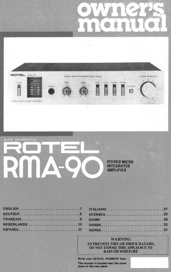
Rotel RMA 90 OM

Extracted text from Rotel RMA 90 OM (Ocr-read)


Page 2

llllillSll

STEREO MICRO INTEGRATED AMPLIFIER RMA-90

INTRODUCTION

We at Rotel want to thank you lor purch-ing
our audio product.

Hotel audio products are designed to use the
latest electronic technology, and they incorpo-
rate our long experience a specialist manufac-
turer of audio emiprrtent. We are confident
that you will find satislaction In the hip:
mallty sound and top performance. and that
you will Iind pleuure in the Iunctinnal beauty
achieved through human~engineering concept.
Belore starting operation, please read this
instruction manual thoroughly and acquaint
yoursell with the proper mode cl using the unit
and all its connections.

We hope you will enjoy top-notch performance
for many years to come.

BEFORE ENJUVMENT/POWER SUPPLY

Follow the instructions below Ior maximum

salety:

1. Use a wall outlet or hotel RMR-W tor
rim lively

Be sure to connect the AC line cord directly to

a household wall outlet or Rotel RMR-QO, and

not to an auxiliary outlet on another compo

nent, Be certain that the outlet voltage matches

the electrical rating oi the unity found on the

rear panel name plate.

2. Connecting and removing ac cord

Be sure to connect or disconnect the AC line

cord only alter turning o" the power switch to

prevent possible shock noise or damage to

the speakers.

3. Venue. the unit wall

Never block any ventilation holes at the top

and bottom of the unit. Besure also to provide

ample ventilation space around the unit. Poor

ventilation may result in damage due to exces-

sive heat.

4. Do not 09'! the clsinet

In order to avoid electric shock or damage to

the component, never open the cabinet. If a

Ioreim obiect lells inside the unit by mistake,

turn the power oil, disconnect the wall plug.

and consult a qualified electrician or your

dealer.

6. Installation

Be sure to place the unit in a level and flat place

where it is tree from humidity, vibration. him

temperature and not exposed to direct sunlight.

Ba caretul not to place the unit in a highly

enclosed place such as near a wall or on a

bookshelf. A poor ventilation will cause unde~

sirable etlectt to the unit,

6. Moving the unit

When transporting, remove the AC cord lrorn

the stall outlet and all other connected cords on

the rear panel to prevent wire breakage and

short circuits.

7. II the unit pea wet

It the unit should get wet, immediately discon-

nect the AC cord, and consult your dealer or a

qualilied electrician.

e Cleaning and maintenan-

Do not use chemicals such as benzine or thin~

ners on the front panel. Always use a salt, dry
cloth to clean the unit.

9. Owners mutual

Keep the owner's manual near the unit, and
record the serial number (found on the rear
panel) on the cover.

EXCLUSIVE NOTE FOR U.K.

If your unit comes with a 2-core cable
without a plug. make certain live and
neutral leads are connected to the proper
terminals. Check that the terminals are
screwed down Iirmly and no loom strands
ol wire are present.

IMPORTANT: The wires in this mains lead
are coloured in accordance with the follow

ing code:
BLUE: NEUTRAL
BROWN: LIVE

As the colours of the wires in the mains lead
of this apparatus may not correspond with
the coloured marking identifying the
terminals in your plug proceed at lollom.
The wire which is coloured BLUE must be
connected to the terminal which is marked
with the letter N or coloured BLUE or
BLACK. The wire Mtich is coloured
BROWN must be connected to the terminal
which is marked with the letter L or colour
ed BROWN or RED.

AR: SPEAKER AIRIGHT
AL: SPEAKER AILEFT

BR: SPEAKER B/RIGHT
BL : SPEAKER B/RIGHT

7 AR

|l[

SPEAKER IMPEDANCE
A or a are or monaspxn

SPEAKER

RlGr-tt LEFT

SPEAKERS

The unit allows hookup 0' two speaker sys-
tems. Use speaker systems with impedance
ratings ol 8-16 ohms. Betore hooking up your
speaker system, be sure to check its impedance,
which should be indicated either on the back of
the speaker, or in the speaker instruction mam
ual,

HOOKING UP AND SELECTING
SPEAKERS

On the rear partel oi the RMA-QO are two sets
of speaker tarrninalsl "A" and ",B to which
two speaker systems may be connacted. Con-
nect the speaker leads ol the rifltt-hand speaker
to terminals R" of A" (or I, and the
speaker leads 0' the Ielt-hand speaker to ter-
mina L" of A" (or "3"). Make sure that the
"+" speaker lead is connected to the "e" ter-
minal, and the "-" lead to the --" terminal,
Strip 1.0cm (3/8") at the polyvinyl chloride
insulation lrorn the end of each speaker lead.
Twist the exposed strands timtly, and secure
the end with a touch of solder.

The termian are the pushrinsert type. Insert
the and of the lead into the hole mile pushing
on the button. Then ralaue the button; the
hole will close and the cord is Iirmly fixed.

A slide switch (speaker selector) on the rear
panel is used to select the speaker syltem.
Set the selector to A to activate the speaker
system connected to the speaker terminals
A, and set to B for the speaker system connects
ed to the speaker terminals 3.

,_ AL

, BL

if? U

L , a, .4

SPEAKER SELECTOR