Rotel RE 1010 OM
This is the 7 pages manual for Rotel RE 1010 OM.
Read or download the pdf for free. If you want to contribute, please upload pdfs to audioservicemanuals.wetransfer.com.
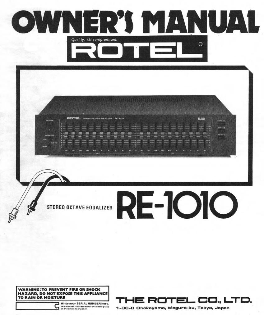
Extracted text from Rotel RE 1010 OM (Ocr-read)
Page 1
OWNERI MANUAI.
Quamy. Uncompromtsed
¢ :7/ STEREO OCTAVE EQUALIZER RE-IOIO
I
k,
I
WARNINGHO PREVENT FIRE 0R SHOCK
HAZARD, DO NOT EXPOSE THIS APPLIANCE
7° m °R "mm" THE HOTEL- CD., I-TD.
3 Will: you! SERIAL NUMBER hem
:2:::$T11'.:;§:.""m"NW" 1 -36-8 Ohokayama, Meguro-ku, Tokyo, Japan
Page 2
INTRODUCTION
We at Hotel want to thank you for
purchasing our audio product.
Rotei audio products are designed
to use the latest electronic techno
logy. and they incorporate our long
experience as a specialist manufac-
turer of audio equipment. We are
confident that you will find satis-
facrion in the him quality sound
and top performance, and that you
will find pleasure in the functional
beauty achieved througt human-
engineering concept. Before start-
ing operation. please read this
instruction manual thorouytly and
acquaint yourself with the proper
mode of using the unit and all
its connections.
We hope you will enjoy top-notch
performance for many years to
come.
INSTALLATION
Be sure to place the unit in a level
and flat place where it is free from
humidity. vibration, high tempera-
ture and not exposed to direct
sunlight. Be careful not to place the
unit in a highly enclosed place such
as near a wall or on a bookshelf. A
poor ventilation will cause undesira-
ble effects to the unit.
POWER SUPPLY CONNEC-
TIDN
For power the umt requires the
normal house electrical current
(AC) Vou may simply plug the
unit to a wall outlet, or to your
amplifiers (or receiver's) switched
or unswitched AC outlet. If ll rs
plugged to a switched outlet, by
Ieavrng the power switch of the
unit on, you will be able to main-
tarn switching control for the
equalizer with your amplifier or
receiver. If it is connected to an
unswitched outlet, like connecting
to a wall outlet you must use the
equalizers own power switch for
swrtchrng control.
CAUTION Do not apply power
wrthout first making sure the pro-
per connections are completed, If
you live in U.K. and your unit
comes wnh 2-C0rt: c01d wrthout a
plug, be sure to read the exclusive
caution for UK.
FUNCTION OF THE EOUA-
LIZER
Before using your unit, please read
over this brief explanation of the
functions of the equalizer.
As you probably know, program
sources are made up of records,
tape recordings, and AM/FM broad-
casts. The production of the
electric signal that creates this
sound is achieved through various
methods of energy conversion:
through the mechanical vibration of
the cartridge needle as it traces the
groove in the case of records;
through a magnetic signal in the
case of tape recordings: and
through radio waves in the case of
AMIFM broadcasts. In all of these
methods it is difficult to avoid
alterations in sound characteristics
that accompany reproduction, but
such alterations are particularly
conspicuous in the case of records.
Notice the frequency characteristics
for most standard cartridges as
shown in fig. 1 - you can notice
the increase that occurs in the
higher ranges. This is thought to
be due to the impedance of the
cartridge, the input power
impedance of the amplifier, or to
the mutual influence of these two.
As long as the characteristics of
the rest of the sound circuit -
(de) 9- 1
1
1K
rue) F5!- 2
exctuswe Note FOR
u.l<.
If your unit comes with a 24
core cable without a plug, make
certain live and neutral leads
are connected to the proper
terminals. Check thll the ter-
minals are screwed down firmly
and no loose strands of wire
are present.
lMPORTANT: The wires in this
mains lead are coloured in
accordance with the following
code:
BLUE: NEUTRAL
BROWN: LIVE
As the colours of the wires in
the mains lead of this apparatus
may not correspond with the
coloured markings identifying
the terminals in your plug pro-
ceed as follows.
The wire which is coloured
BLUE must be connected to the
terminal which is marked with
the letter N or coloured BLUE
or BLACK. The wrre which rs
coloured BROWN must be con»
nected to the terminal which is
marked with the later L 0r
coloured BROWN or RED.
_o
(Hz)
400 K