Rotel RD 500 OM
This is the 6 pages manual for Rotel RD 500 OM.
Read or download the pdf for free. If you want to contribute, please upload pdfs to audioservicemanuals.wetransfer.com.
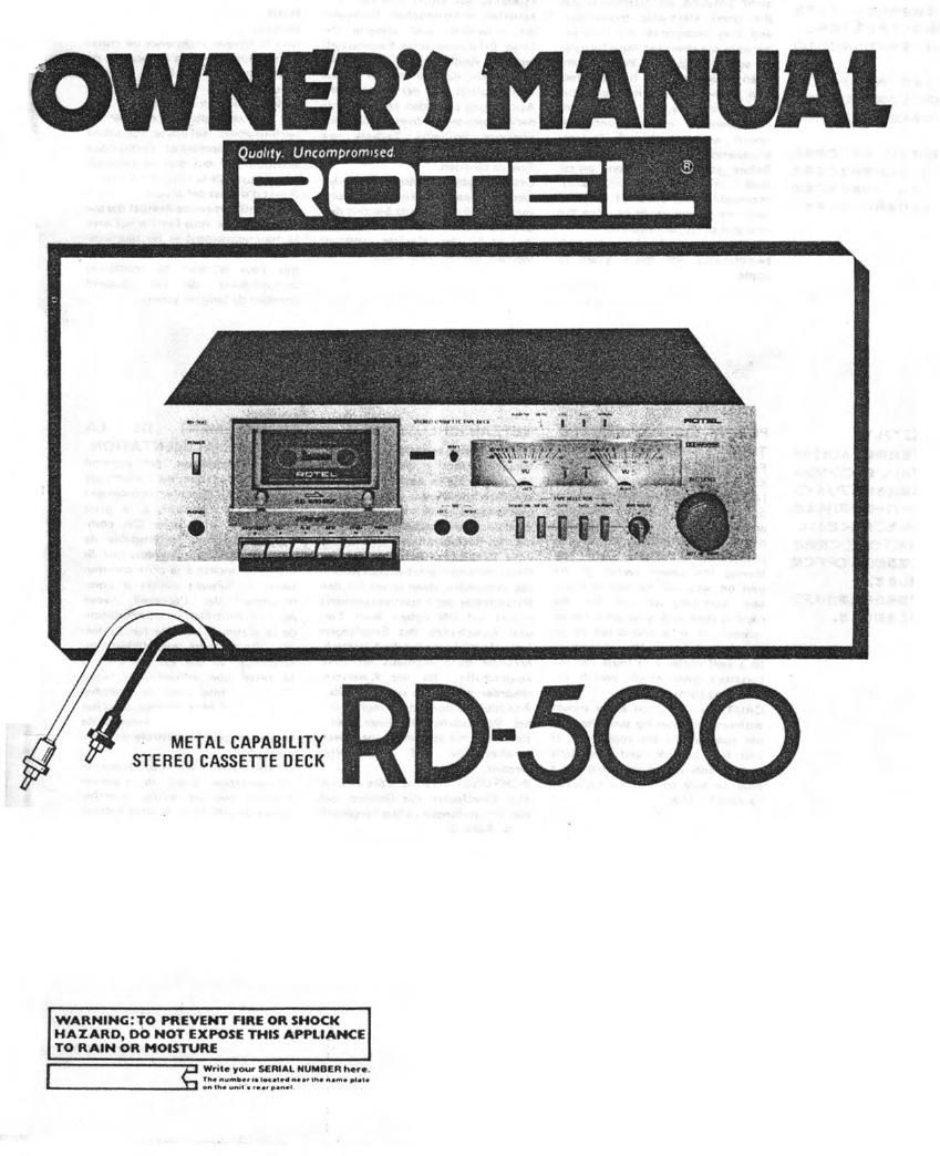
Extracted text from Rotel RD 500 OM (Ocr-read)
Page 1
OWNERS NANUAI.
Quality Uncampromvsed
STEREO CASSETTE DECK
WARNINGITO PREVENT FIRE 0R SHOCK
HAIARD, DO NOT EXPOSE THIS APPLIANCE
T0 RAIN OR MOISTURE
It. you SERIAL NUMBER W0.
1». a.-. .. mm. .nv In. an. .m-
.. IM om . nt-vbn-l
Page 2
INTRODUCTION
We at Hotel watt to thank you for
purchasing ouraudio product. Rotel
audio products are designed to use
the latest electronic technology,
and they incorporate our long ex-
perience as a specialist manulacturer
oI audio equipment. We are con-
Iident that you will Iind satislac~
tion in the high quality sound and
top perlormmoe, and that you will
find pleasure in the Iunctronal
beauty achieved through human-
engineering concept.
Belore starting operation. please
read this instruction manual
thoroughly and acquaint yoursell
with the proper mode oI using the
unit and all its connections.
We hope you will enjoy topnotch
performance tor many years to
come.
POWER SUPPLY CONNEC-
TION
For power the untt requires the
normal house electrical current
(Acl. Vou may simply plug the
unit to a wall outletl or to your
ampliliers (or receiver's) switched
or unswitched AC outlet. ll it is
plugged to a switched outlet, by
leavrng the power switch ol the
unit on you will be able to main»
tain swrtching control (or the
cassette deck with your amplilier or
receiver. II it is conneued to an
unswitched outlet, like connecting
to a wall outlet you must use the
cassette's own paws" switch Ior
swttching control.
CAUTION - Do not apply power
without Iirst making sure the pro»
per connections are completed. II
you live in UK. and your untt
comes with Zoom cord without a
plug be sure to read the enclusive
caution Ior UK.
INSTALLATION
Be sure to place the mm m a level
and Ilat place where II is lree Irom
humttlrly. vibration, high temnell
aturc and not exposed to d-rect
sunlight
8e carelul not to place "19 unit in .1
highly enclosed place such as near
a wall or on a mokshrfll A poor
VIflllIrJIIOH will cause undesirable
ellccts to mi.- tHII
CONNECTION TO RE-
CEIVER DR AMPLIFIER
Connect the unit's rear panel ter-
minals to the TAPE MONITOR ter-
minals oI your amplifier, using
the RCA cords.
The units LINE IN terminals
should be connected to the TAPE
MONITOR OUT terminals of the
arnplilier. and the LINE OUT
terminals to the TAPE MONITOR
lN terminals oI the amplilter. Be
certain to properly match right and
Ielt terminals between components.
MICROPHONE AND HEAD-
PHONE CONNECTION
Microphone and headphones may
be connected to the unit using the
respective jacks on the lront
panel. When using stereo micro-
phones, be sure connections are
made properly to the left and right
jacks.
Nota: Microphones must not be
connected except when carrying
out microphone recording.
EXCLUSIVE NOTE FOR
U.K.
ll your unit comes with a 2-
cora cabl without a charm
cartlin live and neutral leads
are connected to the proper
terminals. Check that the tar-
minals are screwed down lirmly
and no loose strands oi wire
are present.
IMPORTANT: The wires in this
mains lead are coloured in
accordance with the Iollowing
coda:
As the colours ol the wires in
the mains lead at this apparatus
may not correspond with the
coloured markings identilying
the terminals in your plug prov
caed as Iollows.
The wire which is coloured
BLUE mu be connected to the
terminal which is marked with
the letter N or coloured BLUE
or BLACK. The wire Mich is
coloured BROWN must be con»
nectad to the terminal which is
marked with the later L or
BLUE: NEUTRAL
BROWN: LIVE coloured BROWN or REO'
AMPLIFIER
(RECEIVER) TAPE
MONITOR l