Rotel RD 1001 OM

This is the 6 pages manual for Rotel RD 1001 OM.
Read or download the pdf for free. If you want to contribute, please upload pdfs to audioservicemanuals.wetransfer.com.

Page: 1 / 6
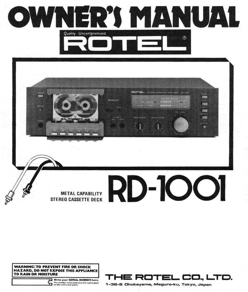
Rotel RD 1001 OM

Extracted text from Rotel RD 1001 OM (Ocr-read)


Page 1

OWNERS MANUAL

Quality Uncompvomvsed

-
METAL CAPABILITY
STEREO CASSETTE DECK

WARNlflGt'I'O PREVENT FIRE 0R SHOCK
HAIARD, DO NOT EXPOSE THIS APPLIANCE

70 um on "05111:" 0.. "mum, THE HOTEL CD" l-TD-


1 -36-8 Dhakayama. Meguro-ku, Tokyo. Japan

Page 2

INTRODUCTION

We at Hotel want to thank you for
purchasing our audio product.
Rotel audio products are desagned
to use the latest electrontc techno
logy, and they lncorporate our long
experience as a specialist manulao
turer of audio equipment We are
confident that you WIII find SaIlSr
faction tn the high quality sound
and top performance, and that you
will Iind pleasure in the Iunctional
beauty achreved through human-
engineering concept. EEIQJE start
ing operation, please read this
instruction manual thoroughly and
acquaint yourself With the proper
mode at uslng the unit and all
its connections.

We hope you Will enoy top~notch
performance for many years to
come

POWER SUPPLY CONNECTION

For power the unit requires the
normal house electrical current
(AC). You may simply plug the
unit into a wall outlet, or into your
amplifiers switched or onswitched
AC outlet If it is plugged into a
switched outlet. by leaving the
power switch of the unit on, you
will be able to maintain switch-
ing control for the RD-1001 with
your amplifier. If it is connected to
an unswitched outlet, like connect~
ing to a wall outlet you must use
the RD«|001's own power switch
for switching control.

CAUTION: Do not apply power
without first making sure the
proper connections are completed.
If you live in UK and your unit
comes with 2-core cord without a
plug, be sure to read the exclusive
caution for U.K.

U.K.

are present

EXCLUSIVE NOTE FOR

lMPORTANT The wrres in this
mains lead are coloured
accordance wnh the lollowmg

As the colours ol the wlrus tn
the mains lead at thts apparatus

II your unit comes wtth a 2, may not correspond wnh the
core cable Without a plugvmakel
certain live and neutral
are connected to the proper
terminals. Check that the ter
mlnals are screwed down hrme
and no loose strands ol

coloured marktnqs ldentllylng

leads lht: terminals in your plug pro

coed as Iollows
The wlre Wthh is coloured
BLUE must be connected to the

wue terminal which ls marked wrth

the letter N or coloured BLUE
or BLACK The wlre which IS
" coloured BROWN must be cortr
nected to the terminal which is

wde marked Wllh the leter L o,
3:33,, TIE/Em coloured BROWN or RED.
INSTALLATION CONNECTION T0 INTE-

Be sure to place the unit ln a level
and Ilat place where it IS free from
humidity, vibration, high tempera-
ture and not exposed to direct
sunlight, Be careful not to place the
unit in a highly enclosed place such
as near a wall or on a bookshell, A
poor ventilation will cause undesiraa
ble eliects to the unit,

TAPE

lN OUT

MONITOR

GRATED AMPLIFIER

Two pairs of RCA cords tor LINE
lN/OUT extend out from the rear
panel of the cassette deck. The cord
from the LINE IN terminals of the
deck should, be plugged into the
TAPE MONITOR OUT terminal of
the amplifier, and the cord from
LINE OUT terminal to the TAPE
MONITOR IN terminal. RCA cords
with white plugs are Ior left ohan-
rtel (Ll connection, and cords with
red plugs are for right channel (RI.

AMPLIFIER (REAR PANEL)

CASSETTE DECK