Rotel RCX 400 OM

This is the 7 pages manual for Rotel RCX 400 OM.
Read or download the pdf for free. If you want to contribute, please upload pdfs to audioservicemanuals.wetransfer.com.

Page: 1 / 7
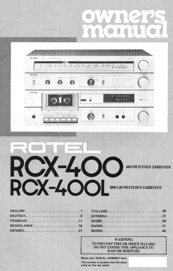
Rotel RCX 400 OM

Extracted text from Rotel RCX 400 OM (Ocr-read)


Page 1

RCX-4oo
RCX-4oowWW

ENGLISH .......................... 1 ITALIANO ........................ . 26

DEUTSCH .......................... 6 SVENSKA ......................... . 31

FRANCAIS ........................ 1 1 SUOMI ............................ 36

NEDERLANDS ................ 16 DANSK ............................ 41

ESPANO L ......................... 21 NOHSK ............................ 46
WARNING

TO PREVENT FIRE 0R SHOCK HAZARD.
DO NOT EXPOSE THIS APPLIANCE T0
RAIN 0R MOISTURE

Wl'iu Your SERIAL NUMBER hm.

Thu uumbor Is locum mar flu mm-
nln- on the rur pal-I.

Page 2

[NlilISII

AM/FM STEREO CASSEIVER RCX-400
MW/LW/FM STEREO CASSEIVER RCX-4OOL

INTRODUCTION

We at Rotel want to thank you for purchasing
our audio product.

Hotel audio products are designed to use the
lalest electronic technology, and they incomdr
rate our long experience as a specialist manuiac-
turar oi audio equipment We are confident
that you Wlil find satisfaction in the high
quality sound and top performance, and that
you will lrnd pleasure in the functional beauty
achieved through humenengineermg concept.
Belore starting operation, please read this
instruction manual thoroughly and acquainl
yoursell with the proper mode of ullng the unit
and all its connections.

We hope you will enjoy tnprnotch performance
for many years to coma.

BEFORE ENJOYMENT/
POWER SUPPLY

Follow till inflmctionl below he! maximum
surety:

1. Us- a wall mddt for power mpply

Be sure to connect rlic AC lino cord directly to
a household wall outlet. and not to an auxiliary
outlet on another component. Be certain that
the outlet voltage matches the electrical rating
oi the unit, found on the rear panel name plate.
2. Connecting Ind ramming AC cord

Be sure to connect or disconnect the AC line
card only alter turning on the power switch to
prevent possible shock noise or damage to
the speakers

3, Ventilete the unit well

Never block any ventilation holes at the top
and bottom of the unit Be sure also to provide
ample ventilation space around the unit. Poor
ventilation may result In damage due to excesr
sive heat.

4. Dn nut opln tho chino!

In order to avoid electric shock or damage to
the component, never open the cabinet. If a
foreign object lalls inside the unit by mistake,
turn the power 0. disconnect the well plug,
and consult a qual d electrician or your
dialer

5. Imulletiort

Be sure to pince the unit In a level and at place
where it is free from humidity, vibrallon, high
temperature and not exposed to d ect sunlight.
Be ooreiul not to place the unit in a highly
enclosed place such as near a wall or on a
bookshelf. A poor ventilation will cause under
sirable eifncts to the unit.

at Moving the unit

When transporting, remove the AC cord from
the wall outlet and all other connected cards on
the mar panel to pmvont wire breakage and
short circuiu.

7. II the u it on: WII

II the unit should get wet, immediately discon
nect the AC cord, and consult your dealer or a
qualified electrician.

8. Cleaning and maintenance

Do not use chemicals such as benzln. or t

ners on the iront panel. Almys use a salt, dry
cloth to clean the unit.

9. Owner's manual

Keep the owner's manual near the unit, and
record the serial number (found on the rear
panel) on the cover.

EXCLUSIVE NOTE FOR U.K.

ll your unit comes WIIh a Zrcora cable
without a plug, make certain live and

neutral leeds are connected to the proper

terminals. Check that the terminals are
screwed down firmly and no loose strands
of wire are present.

IMPORTANT: The wires 1 this main; lead

REAR PANEL CONNECTIONS

Spas ker System

Use speaker system wnh impedance ratings of
4-16 ohms aerate hooking up your speaker
system, be sure to check its impedance, which
should be indicated on the back of the speakar.
Connect leithand speaker leads to SPEAKER
terminals "L" on the rear panel, and rlghtvhand
speaker leads to terminals R". Make sure that

R

are coloured In accordance with the Iolldw»

ing code:
BLUE: NEUTRAL
BROWN: LIVE

As the colours of the wires in the mains lead
ol this apparatus may not correspond with
the coloured markings identifying the
terminals in your plug proceed as «shows
The wire which is coloured BLUE must be
connecmd to the terminal which is marked
with the letter N or coloured BLUE or
BLACK. The wire which is coloured

BROWN must be connected to the terminal
which is marked with the letter L or colour-
ed BROWN or RED.

the "+" speaker lead is connected to the "tr
terminals on the rear panel, and the "-" lead to
the "7 terminals.

Strip about |.Dcm (3/8") of the vinyl insular
tion all the end ol Each speaker lead, twist the
exposed strands] and secure the end with a
touch of solder

To connect the lead to the terminal, push the
button on the terminal and Insert the and at
lead into the hole. and then release the button.

L