Rotel RA 412 OM
This is the 5 pages manual for Rotel RA 412 OM.
Read or download the pdf for free. If you want to contribute, please upload pdfs to audioservicemanuals.wetransfer.com.
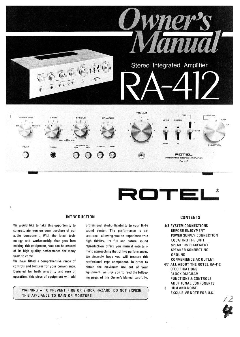
Extracted text from Rotel RA 412 OM (Ocr-read)
Page 1
., (Err -9- exam
- Mamas -
one:
Q
TREELE
reo Integrated Amplifier
VOLUME
BALANCE
ena
LouoNEes
.93. $3
MUYING
i~ Tl
museum
I
a; %, souncE
a
m
HOTEL
enema
L l
. 9 , W
Aux
FUNCTION
lNTEGfiATED srsnsu AMPLIFIER
undue
RDTEU
INTRODUCTION
We would like to take this opportunity to
congratulate you on your purchase of our
audio component1 With the latest tech-
nology and workmanship that goes into
making this equipment, you can be assured
of its high quality performance for many
years to come.
We have fitted a comprehensive range of
controls and features for your convenience.
Designed for both versatility and ease of
operation, this piece of equipment will add
professional studio flexibility to your Hi-Fi
sound center. The performance is ex-
ceptional, allowing you to experience true
high fidelity.
reproduction offers you'musical entertaine
ment approaching that of live performances.
We sincerely hope you will treasure this
Its full and natural sound
professional type component. In order to
obtain the maximum use out of your
equipment, we urge you to read the follow-
ing pages of this Owner's Manual carefully.
(
WARNING - TO PREVENT FlRE OR SHOCK HAZARD, DO NOT EXPOSE
THIS APPLIANCE TO RAIN OR MOISTURE.
J
2/3
4/7
CONTENTS
SYSTEM CONNECTIONS
BEFORE ENJOYMENT
POWER SUPPLY CONNECTION
LOCATING THE UNIT
SPEAKERS PLACEMENT
SPEAKER CONNECTING
GROUND
CONVENIENCE AC OUTLET
ALL ABOUT THE ROTEL IRA-412
SPECIFICATIONS
BLOCK DIAGRAM
FUNCTIONS & CONTROLS
ADDITIONAL COMPONENTS
HUM AND NOISE
EXCLUSIVE NOTE FOR UK.
/42:
Page 2
System Connections
BEFORE ENJOYMENT!
For safety sake keep in mind the following
cautions:
1. Do not connect the unit to the AC
power line without speakers connected be-
forehand.
2. Make sure also that the power switch is
left offland the mastervolume control is
set at minimum before plugging in the
power cord to a wall outlet.
3. Speakers
3) Impedance -
rated at 8 ohms or higher up to 16 ohms.
in the event your speakers are rated at
4 ohms or lower than desired 8 ohms,
Be sure to use speakers
you may operate with one pair of such
type of speakers at a time but never
two pairs of speaker system simultane-
ously. This measure is to prevent any
severe overload and distortions from
happening due basically to too low im-
pedance to 'draw excessively high cur-
rent. When you are uncertain on your
speakers rating values, consult with the
dealer or store you purchased.
Connection - Before connecting speaker
leads to the terminals on appliance make
sure also no loose stray strands of wire
is left in order to prevent any shorting
between speaker leads or terminals to
main chassis. This shorting malfunction
may be common cause of blown fuses
or overload.
4. Always use the fuse, if necessary to
replace, of same type and rating as the one
installed on the unit. Replacing fuse in-
correctly with higher rating will defeat the
purpose of protection and may cause severe
damage instead.
5. Furnished Convenience AC Outlet
(a) Do not insert or remove plug from any
convenience AC outlet supplied on the
appliance while the appliance is con-
nected to power. Also do not insert
foreign object, other than a proper plug,
into the convenience AC outlet.
(b)Do not connect other appliance(s) to
convenience AC outlet if its/their total
power consumption exceeds maximum
rated watts labeled next to the outlet.
b
POWER SUPPLY CONNECTION
For power the unit requires the normal
house electrical current (AC). Simply plug
the unit to a wall outlet.
If in any doubt- about connecting to the
power source, consult a qualified electrician.
CAUTION - Do not apply power to the
equipment without first making sure that
speakers are connected properly and that
the units VOLUME control is set to mini-
mum. If you live in U.K. and your unit
comes with More cord without a plug, be
sure to read the last page of this manual
before connecting to power.
LOCATING THE UNIT
Although the unit normally does not deve-
lope high heat, it should be placed in such a
way that its ventilation system will not be
impeded. Place the unit on a hard surface -
any conveniently located shelf or table
where not affected by heat or moisture.
Leave at least 5 cm (2 inches) clearance on
each side and in the rear of the unit, and
about 10 cm (4 inches) above the unit.
Never directly place an object on the top of
the unit.
SPEAKERS PLACEMENT
NOTE -- Check speakers rated impedance
as instructed on this page.
STEREO TUNER
STEREO
RECORD PLAYER
1. MAIN SPEAKERS - Referred to a pair
of speakers connected to the SPEAKER 1
terminals on the unit's rear panel. Place the
main speakers against a wall or on a shelf so
that they face your selected listening
position and are equal distance from you.
For optimum stereo effect, they should be 3
to 4 meters (10 to 15 feet) apart and, if
possible, at about ear level height. You may
determine best locations to suit your
personal tastes and listening conditions.
2. REMOTE SPEAKERS- If you wish to
enjoy stereo sound in another room, you
can connect another pair of speakers to the
SPEAKER 2 terminals. Though you may
require long cables between the unit and the
O STEREO
TAPE
D% RECORDER
(b
GND
remote speakers, make sure they are not
longer than If: to 20 meters (50 to 60 feet)
in length and that they are of heavy duty
shielded type in order to prevent loss of
volume level. Following the procedure
described in the iteml above for placing
the remote speakers.
SPEAKER CONNECTION
Caution: Do not apply power to the unit
until the speakers are connected properly as
described below. V
As shown in Fig. 2, the speaker terminals
are quick-connect push-insert type, and are
arranged into two boards, one for
SPEAKER 1 (main) and the other for
LEFT SPEAKER-l RIGHT
SPKR 2
LEFTrE-D-
wRIGHT
-O-UJ m
o! , , llll
(M) (ii RIGHT
=lilGliT L-
-SPKR FUSES SWITCHED-
OUT AC OUTLET
OLEFT SWITCHED LEFT
2+4: [ll
POWER
«2
STEREO
12PHONo T-UNER Au REC/PE]!
LEFT(\\ .35
g g RIGHT
RECORD PALYER
//
1
STEREO
8»TRACK PLAYER
OPENGHERE
STEREO
TAPE RECORDER
OUUDD
o Ooooo on
llllmnlllll0
Fig.
LEFT SPEAKER-2
RIGHT
RIGHT
LEFT F594 2
SPEAKER 2 (remote). Push back the tab on
each terminal, slip the bare wire at the free
end of the speaker lead into the opened jaw
of the terminal, and release the tab to grip
the bare wire in the jaw. (Note: if necessary,
after stripping each end of speaker leads to
obtain a bare wire, twist the bare strands
together so it will be easy to insert and also
prevent shorting among stray strands.) Make
sure the positive (+) lead of each speaker is
connected to the (+) terminal and the
ground (-) lead to the (-) terminal, and
right to RIGHT and left to LEFT.
GROUND (EARTH)
The GROUND screw terminal is provided
on the rear panel to provide means for all
equipment chassis to be at the same
potential in a Hi-Fi installation.
CONVENIENCE AC OUTLET
The outlets marked SWITCHED on the rear
panel provide power and switching control
to whatever component you may wish to
connect to the unit. For example, if you
connect the power cord of your record
player to the outlet, the record player will
be activated and deactivated by the power
switch on the unit.
Caution: Do not connect components
whose total power consumption exceeds
maximum power rating marked on the
outlets.