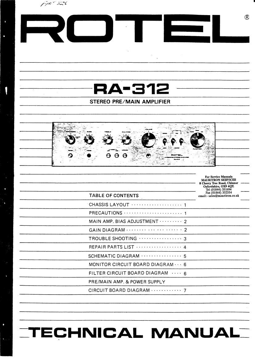
Rotel RA 312 Service Manual
This is the 11 pages manual for Rotel RA 312 Service Manual.
Read or download the pdf for free. If you want to contribute, please upload pdfs to audioservicemanuals.wetransfer.com.
Extracted text from Rotel RA 312 Service Manual (Ocr-read)
Page 1
v 4/
///c M ~
HOTEL:
PIA-312
STEREO PRE/MAIN AMPLIFIER
For Serflce Manual-
MAURHRON SERVICES
8 Cherry The Road, Chlnlmr -
°§$26¥§2§33§¥6§?
TABLE OF CONTENTS _ emaiaiafiléfiifiifimk _
CHASSIS LAYOUT -------------------- 1 -
PRECAUTIONS ....................... 1
MAIN AMP. BIAS ADJUSTMENT --------- 2
GAIN DIAGRAM ................... . 2
TROUBLE SHOOTING ---------------- 3
REPAIR PARTS LIST ------------------ 4
SCHEMATIC DIAGRAM ---------------- 5
MONITOR CIRCUIT BOARD DIAGRAM - -- e
FILTER CIRCUIT BOARD DIAGRAM ..4. 5
PRE/MAIN AMP & POWER SUPPLY
CIRCUIT BOARD DIAGRAM ------------ 7
:TECHNICAL MANUAL:
Page 2
('3
CHASSIS LAYOUT
53T95n?5"!"7
$9,'Power Switch
S2, Speaker Selector
Headphone Jack
Bass Control
Treble Control
56, Loudness Switch
S7, High Filter Switch
Balance Control ..
58, Low Filter r .
Volume Control 1- '
85, Mode Switch. ' 'K
S4, Tape Moniter-l Switch.
83. Tape Moniter-Z Switch.
51. Function Selector
lC401, Phono Amp. IC.
Phono Din Jack i- g ,-
0613, Power Amp. (L-ch) I
Input Terminal
0611, Power Amp. (L-ch)
Tape Monitor Din Jack
Tape Monitor Terminal
0612, Power Amp. (Fl-ch)
0614. Power Amp. (R-ch)
Speaker Fuse
F901, AC Fuse
Speaker Terminal 1 and 2
AC Outlet 1 and 2
T001, Power Transformer
PRECAUTIONS
Always disconnect the chassis from power line when
soldering. Turning the power switch OFF is not enough,
Power line leakage passing through the heating element
may destroy the Transistors.
Never attempt to do any work on the transistor
amplifiers without first disconnecting the AC line cord
and waiting until the power supply filter capacitors have
discharged.
Replacement for output and driver transistors, if
necessary, must be made from the same hfe group as
the original type.
If one output transistor burns out (open or short)
oooWoo
®@@®@@@®®®®®®©
always remove all the output transistors in that channel
and check the bias adjustment, the control and other
parts in the network with an ohm-meter before inserting
a new transistor. All transnstors in one channel will
be destroyed it the base biasing circuit is open on the
emitter end,
When mouting a replacement power transistor, be sure
that the bottom of the flange, the mica insulators and
the surface of the heat sink are free of foreign matter,
for they may cause transistors failure.
Silicon grease must be applied between the transistor
and the mica insulator, and between the mica insulator
and the heat conduction