Rotel RA 212 OM
This is the 3 pages manual for Rotel RA 212 OM.
Read or download the pdf for free. If you want to contribute, please upload pdfs to audioservicemanuals.wetransfer.com.
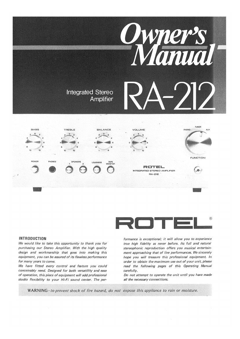
Extracted text from Rotel RA 212 OM (Ocr-read)
Page 1
Integrated Stereo
Amplifier
BASS THESLE BALANCE
u a o '
2 e 2 a 2 e
\ 4 A 4 4 A 4
w... a 6 a E »* E
E . _ 5 B E B E
0 1C 10 K] L R
pnwan wanes awakens LDUDNESS
a
39er
INTRODUCTION
We would like to take this opportunity to thank you for
purchasing our Stereo Amplifier. Wit/7 the high quality
design and workmanship that goes into making this
equipment, you can be assured of its flawless performance
for many years to come.
We have fitted every control and feature you could
conceivably need. Designed for both versatility and ease
of operation, this piece of equipment will add professional
studio flexibility to your Hi-Fi sound center. The per-
mes
Momma
Q
TUNER
mono Aux
fro-N 7 ,
«we 4
_, \ 5 _'
u " 10 fig
FUNCTION
INTEGRATED STERED AMPLIFIER t0 3
fiA-EVE
RDTEU
formance is exceptional; it will allow you to experience
true high fidelity as never before. Its full and natural
stereophonic reproduction offers you musical entertain-
ment approaching that of live performances. We sincerely
hope you will treasure this professional equipment. In
order to obtain the maximum use out of your unit, please
read the following pages of this Operating Manual
carefully.
Do not attempt to operate the unit until you have made
all the necessary connections.
WARNINGeto prevent shock of fire hazard, do not expose this [appliance to rain or moisture.
Page 2
FRONT PANEL CONTROLS
aAss CONTROL
When thls knob is turned clock-
vlrlse, bass rs emphasized; when
turned eounterclockvvlse,attenur
ated. wlth the knots set lrl the
center, the flequency response
it llat or normal,
vvlsol
ated
TREBLE CONTROL
When the knob ls turned CIuckr
turned counterclockwise, attEnUr
center, the treouency response
rs flat or normal
BALANCE CONTROL
Thrs knob ls used to edrust the
stereophonic balance When lt re
turned clockvvlse the lelt chan.
nel sound level ls decreased and
when turned counterclockvvlse
the rlght channel sound level
treble ls Emphastzed'l when
With the knob set ln the
decreases.
VOLUME CONTROL
The sound level lneteatet when
the knots is turned clockwlse,
When swltchlng on the power or
the rnput selector, keep lt turned
lully counterclockwrse at rnlnl-
rnutn.
INPUT SELECTOR CONTROL
This is used for selecllon Of pro-
vram sources as applied to tire
PHOND, TUNER and AUX (Er-
L
POWER SWITCH
A push on the swrtch turns on speo
the arnpllller. The reserve AC tor
outlet on the rear panel ls slmuIr
I tsneously turned on and on,
LA PHONES RECEPTACLE
This lack ls used for connectron
OI headphones to enioy prrvate
lrstenlnp
INSTAL LATID N
IMPORTANT, Do not turn on the power swrtch
oelore cornoletlon or proper connections or the
speaker systems and lnputs.
SPEAKER SVSTEMS
Thlt unlt ls eouloped wlth nulnkrccnnccl law-snaD
terminals lor eonnectrng two sets oi speakers.
Cull ett your than. can ul speakers to the
\ErmlnaIs marked SPKHrI Ensure that your
rlsht speaker ls connected to the terrnlnal marked
@and that the ground (7) termlnal on the rloht
speaker ts connected to the lermmaI marked
9 on the extreme lclt or the terminal block
slmllarly, connect your lelt speaker between
the adlacent SPKR-l terrnlnsls marked@ and
e . If you vvlsh to connect a second pelt ol
speakers, connect thern to SPKR-Z termlnals m
the manner dcscrlbed above
Caution: Erlsure that the speaker leads are
fastened securely to the proper tertnlnals, and
that there are no stray strands vvhtch may cause
shortlng between terrnlnels Ir 2 sets ol speakers
are palyed slrnultanecusly, the lmpedence ot each
unlt should not be less than 3 ohms
TURNTABLE
Model RA 212 ls provldzd vvlth one part ol
PHONO lerrnlnels lot connectloh and playback
ot one turntable
Connect RIGHT output pin lack ol turntable
to thc RIGHT oi the PHONO terminals. and
LEET orn lack to the LEFT of the PHOND terrnl~
nals. The output cord lrorn turntable to be
connected to the PHDNO terrnrnals should be as
short as posslble ln order to mmlmlze loss or
hlgh frequency characterlstlcs. When uslhg a
SPEAKER SWITCHES
operatlorl Of SFKer and sPl
the rear panel,
ker system selector swrtchet
lrldlvldual or slmultaneous
notes wdl
or monltorlng The
speaker syvltches may he turned
ollwhen using headphones only
turntable eoutppcd vvrthaoround wlre. cork
nect the ground wlre to he CND terminal oi [his
unlt ll your turntable cornes wlth e DIN plug,
slrnply plug it to the DIN socket PHONO. It
you wtsh to use a cerarntc Canndge, move the
MAG/CER selectorswrtch down to CER posltron
It the canvldge ls magnetic, leave .t at MAG
postlton
AM/FM TUNER
For astereo tuner, the RIGHT and LEFT outputs
on the rear panel ol the tuner should be con-
nected to the TUNER terrnlnals on the rear panel
ol thls unlt. Connect the RIGHT output cord
hunt the tuner to TUNER terminal RIGHT of
thls untt, the LEFT output cord to TUNER
[ermlnaI LEFT.
CONNECTION TO THE AUX TERMI-
NALS
Output of varlous tvpes oi audlo equipment can
be connected to the tennlnals, such as 3 track
tape player
TAPE RECORDER
The TAPE MONITOR ternnnals on the rear panel
ol thls unlt are tor connectlon oi tape recorder
Input and output.
IN (tape olayoack rnputl, or Conneclton oi
tape recorder outputwhen playing back Dre»
recorded tape through thrs unlt,
OUT (tape recovdlng output).,, for connectlon to
the lnput oi a tape recorder tor recording
programs from record player or tuner cunr
nected to thrs unlt.
LouDNESS SWITCH
The human ear becomes less
sensrtlve to low and hloh sounds
when volume level ls low wlth
thls swrtch turned on at low
volume settings, pass and treble
be emphasized lor
natural llstehlne pleasure
mlnels on the rear panel,
PHOND,.,.fcIr llstenlng to rer
cords vlnlh a turntable tour
nectod
TUNER lor llstenlno to AM/
FM broadcatts wrrh a tuner
connected
Aux,, ,for reproduction oi
audlpeornponentspther than
those mentioned abovecon.
nectedtoAUX rnPut ternnnal.
PILOY LAMP
The lamp lrghts up when the
power SleEh is nipped on,
TAPE MONITOR lTAPEl
This Is a monltor svvrtch for a
tape recorder connected to the
TAPE MONITOR terrnlnals on
the rear panel Normally, when
Ilstenlngtp records or FM broad.
casts the svvltch ls kept ln the
SOURCE position
CONNECTION TO THE GROUND (GND)
TERMINAL
when the outputs 0! a recorder player and a tape
recorder are connected to this unit for playback,
any ground wlre from the respeetlve coulpment
should be connected to the ground termtnal or
thrs unlt provrded on the rear panel in order to
prevent hunt and other noises.
CONNECTION To THE Ac OUTLET
Power supply to a record player or a tuner can
he obtarned lrotn thls outlet provlded on the
rear panel ol lhts unlt The outlet .s turned on
and ott vvrth the operation Elf-(he power swrtch
on the Iron! panel. Any euulprnentoonnected to
the outlet should not exceed the lndlcateo power
consumpt.on ratlng oi lsow.
OPERATION
Alter all the connections have been made, turn
on the power switch.
TURNTABLE
ll Connect the turntable output to the PHONO
termlnals on the rear panel ot thls unlt.
2) Set the lnput selector switch on the (tent
panel to the PI-loNO position.
3) Make sure that the tape monltor svlntch ls tn
the SOURCE posltlon,
Al Turn the other control knobs to obtain the
sound level deslred
. REAR PANEL
CONNECTIONS
O ,
=3
- oO
STEREO TURNTABLE
(MAC OR CERAMIC)
MAG/CER SELECTOR SWITCH
SrTRACK STEREO PLAYER
STEREO TUNER
AC OUTLET
-'_-_
STEREO T'AIPE IRECORDER
I
OUT PUT INPUT
LEFT
SPEAKERS-7 RIGHT
+ c +
SWITCHED
+ ,
SPEAKERS-2
:10
Ac POWER CORD
AM/FM TUNER
ll Connect the tuner output to the TUNER
termlnals on the rear panel oi thls u
2) Set the input selector svvrtch on the iront
Panel to me TUNER Posmon.
3) Make sure that the tape monltor swltch ls tn
the SOURCE positron,
4) Turn the other control knobs to pbtaln the
desired level alter the tuner has been tuned In
to the deslred statlon
TAPE RECORDER
Connect the tape recorder lnput and output to
The TAPE MONITOR termlnals on The leaf panel
Of Ihls unit.
RECORDING
ll Make sure that the tape monltor swnch on
the lront panel ts set rntne SOURCE posmon
Set the tnptrt selector svvltch to one pl the
program source oosltlons. PHONo, TUNER
or AUX.
al Pertcrm recordlng operotlon oi the tape rer
corder to record the desired program source
through thls unlt
2
PLAYBACK
ll Press the tape monltor swrtch and set ll ln
the MONITOR posltlon. (In the case ol plav'
back, the Input selector svvltch can be kept in
any posltlon as it ls overrldden at thts Dumas
tron.)
2) Perform a playback operation of the tape
recorder and control the other controls on
thls unlt to may tape playback at the deslred
sound level
STEREO HEADPHONES
Just lnsert to the PHONES rack to enroy prlvate
ltstenrng
TONE CONTROLS
BASS. JO! control oi boss notes,
TREaLE. tor control oi treole notes.
Even when the tone controls are set ln the center
pea-hon. lr ts not always possrcle tc ahtaln an
acoustlcally llat response dependan on program
sources and acoustlc characteristlcs ot the
lrstehlno roprn The tone controls enable the
listener to have an acoustically Ilat response.
However. an excesslve boost oi cats or treble
notes may produce unpleasant results, so the
tone controls should be used only to compensate
tor acoustic reourrements,
INSTRUCTION FOR OPERATION
LOCATION OF OPERATION
Model RA 212 ls designed With one Cunslderar
trons tor heat radlatron
Huwever, rt should not be .nstallad rn an alrtrghl
cablnet or exposed near heat sources.
CONNECTION 0F SPEAKERS
The RArQlZ arnpltirer ts specllled at the load
lrnpedance of 4715 ohms Most speakers are
rated at 5 ohms.
It used at below 4 ohms, thls unlt may burn out
or glve rise to rnal-tunctionlno oi this unlt when
used continuously tor conslderable tlrne Also. do
not use speakers rated below 8 ohms, when
playlno two palr pt speaker systems slmultoneousr
ly
HUM AND NOISE
In any lnph ltdultty lrnlullatlort. hum may be
caused by the lnterconnectlon Of a record player,
tuner and ampl ,as a result or the came; and
drlterent grounds, ll hurn ls experienced vvrth
your anlpllller, dlseonnect everything but the
speakers from the unlt. ll hurn persists, reverse
the Ac Ilne cord Plug tn the record player and
ll hum appears, reverse the record player power
plug and connect a slngle lead Irom the record
player chassts to the ground post on the rear
chassls Connect your other devices tn thls
Hum may also be lndllCEd by detectlve
connectlnc cables or by runnlng these cables too
close to a strong Ac Ileld.