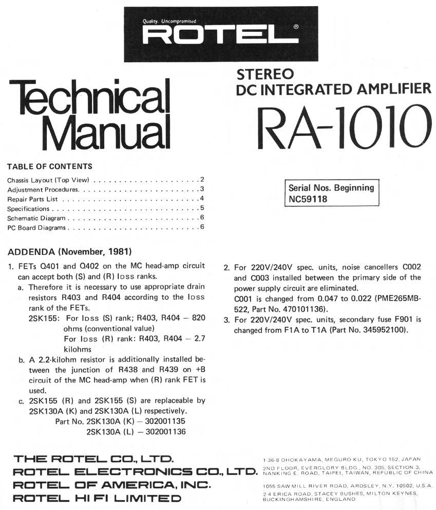
Rotel RA 1010 Service Manual
This is the 6 pages manual for Rotel RA 1010 Service Manual.
Read or download the pdf for free. If you want to contribute, please upload pdfs to audioservicemanuals.wetransfer.com.
Extracted text from Rotel RA 1010 Service Manual (Ocr-read)
Page 1
Quality Untampromnzd
RCTEIJ
Technical
Manual
TABLE OF CONTENTS
Chassis Layout (Top View) ..................... 2
Adjustment Procedures ........................ 3
Repair Parts List ........................... 4
Specifications ............................. 5
Schematic Diagram .......................... 6
PC Board Diagrams .......................... 6
ADDENDA (November, 1981)
1. FETs 0401 and 0402 on the MC head-amp circuit
can accept both (3) and (R) loss ranks.
a. Therefore it is necessary to use appropriate drain
resistors R403 and R404 according to the loss
rank of the FETs.
28K155: For loss (3) rank; R403, R404 - 820
ohms (conventional value)
For loss (R) rank: R403, R404 -~ 2.7
kilohms
b. A 2.2-kilohm resistor is additionally installed be-
tween the junction of R438 and R439 on +B
circuit of the MC head-amp when (R) rank PET is
used.
c. 25K155 (R) and 23K155 (S) are replaceable by
23K130A (K) and 25K130A (L) respectively.
Part No. 25K130A (K) - 302001135
23K130A (L) - 302001136
THE RCTEL CC., LTD.
STEREO
DC INTEGRATED AMPLIFIER
RA-IOIO
Serial Nos. Beginning
NC59118
2. For 220V/240V spec. units, noise cancellers C002
and C003 installed between the primary side of the
power supply circuit are eliminated.
0001 is changed from 0.047 to 0.022 (PME265MB-
522, Part No. 470101136).
3. For 220V/240V spec. units, secondary fuse F901 is
changed from F1A to T1A (Part No. 345952100).
lxnnmiiHKAVArtl/x \IlutJHUKU luKHJ 1a,.) lAPAV
RCTEL ELECTRONICS CC., LII-D. iléiimiff LX23"'§X§I.$XM§~9iifitiftftf331
RCTEL CF AMERICA. INC.
RCTEL HI FI LIMITED
1050 SAW Mill RlVI H mm)» ARHSLEV N v 1050} USA
2 d FHlCA HUM) STAN v HLJSMLS \AlLIUN KEVNFS
BUCKINMHAMSDHHF (NULAND
Page 2
Chassis Layout (Top View)
@0 0906600969111
®®®® @96919
1. FUNCTION SELECTOR 17. POWER TRANSFORMER
2. TONE AMP PCB 18. VOLTAGE SELECTOR
3. VOLUME CONTROL 19. MAIN AMP PCB, L-CH
4. PHONO SELECTOR UNIT 20. FUSE, F001, PRIMARY
5. TAPE MONITOR SWITCH 21. VR601, DC BALANCE ADJ, L-CH
6. INDICATOR DRIVER PCB 22. SPEAKER TERMINALS
7. VR812, R-CH LEVEL IND CAL 23. POWER AMP IC, IC601, L-CH
8. VR811, L-CH LEVEL IND CAL 24. DIN SOCKET
9. TREBLE CONTROL 25. TAPE MONITOR JACKS
10. MID CONTROL 26. POWER AMP IC, |C601', R-CH
11. BASS CONTROL 27. INPUT JACKS
12. POWER SWITCH 28. PHONO AMP PCB
13. SPEAKER SWITCH PCB 29. PHONO SWITCH
14. POWER SUPPLY PCB 30. MAIN AMP PCB, R-CH
15. FUSE, F901. SECONDARY 31. VR601', DC BALANCE ADJ, R-CH
16. PROTECTION RELAY 32. MUTING SWITCH PCB