Revox M 217 Owners Manual 2

This is the 2 pages manual for Revox M 217 Owners Manual 2.
Read or download the pdf for free. If you want to contribute, please upload pdfs to audioservicemanuals.wetransfer.com.

Page: 1 / 2
Revox M 217 Owners Manual 2

Extracted text from Revox M 217 Owners Manual 2 (Ocr-read)


Page 1

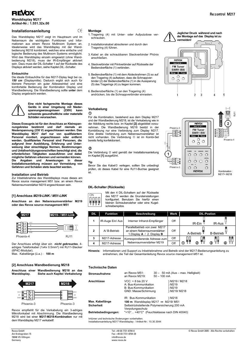
Re:control M217 Revox GmbH Tel: +49 (0) 7721-8704-0 © Revox GmbH 2005 - Alle Rechte vorbehalten Am Krebsgraben 15 Fax: +49 (0) 7721-8704-29 78048 VS-Villingen info@revox.de Germany www.revox.de Wall display M219 Article no.: 1.551.32X.00 Installation The M217 Wall display unit displays the most important information to you in the main room and the additional rooms of a Revox Multiroom system. Additionally, it includes a simple to operate timer for all your wake-up requirements. Ideally, the M217 display unit should be combined with the M218 remote control, which guarantees a simple and logical operation of your multiroom system equipment. If the wall display is used individually (without keypad M218), the IR receiver must be activated. Therefor the DIL switch 1 on the back of the display must be activated; see also chapter DIL-Switch. M217 Installation advice The ideal installation height for the M217 Display is 150 cm / 60 in measured to the centre of the display. This results in a good viewing angle, even for slightly smaller people, and a comfortable operation of the combination of M217 display and M218 keypad. The M218 keypad should be installed below the M217 Display. A unprofessional assembly of this equipment in an environment with products of low-voltage (230V) can cause heaviest health or material damage. This product is intended for the connection to safe voltage circles and must not attached to low- voltage (230 V). The wall display M217 may be installed, attached or removed only from qualified personnel. Qualified personnel are persons, who are entitled due to its training, experience and instruction regarding relevant standards, regulations and rules for the prevention of accidents, who can implement necessary activities and recognise and avoid possible dangers. The data and instructions in this installation guidance must be considered for the avoidance of dangers and damage. Installation and operation For the start-up of the wall display this must be attached at the Revox source management M51 and/or at a Revox additional room amplifier M219. [1] Connection M219-LINK / M51 LINK Connection to the additional room amplifier M219 and/or Revox source management M51 GND GNDA A VCC VCC B B Phoenix-4 RJ11 M219-Link M217 Connection is made using a straight through (not crossed), 4-core telephone cable (1x4x0.5mm²) with an RJ11 plug (6P4C-Modular) Max cable length (o.a.) : 100m – 330 ft [2] IR-LINK Connection of a keypad M218 to the wall display. See also chapter Wiring. Phoenix-3 Phoenix-3 GND GNDIR IR VCC VCC M217 M218 REVOX recommends the use of a 3-core, screened microphone cable. When using a M217-M218- combination the wiring of the keypad takes place directly at the display! Installation 1. Screw the metal supporting ring (4) to the flush box 2. Isolate the installation cable and guide it though the supporting ring (4) 3. Connect the Phoenix connection plug with the cable 4. Combine the connection plug with corresponding Phoenix socket on the backside of the wall display (4) 5. Align the wall display (1) with the corresponding masking frame (3) above the supporting ring (4), so that the catch hooks (2) of the wall display are in line with the gap (5) of the supporting ring. 6. Press the wall display (1) smoothly onto the supporting ring (4) till the catch hooks clip in. Wiring c The wiring of the combination, consisting of the wall display M217 and the keypad M218, is done as illustrated on the right side resp. in chapter [2]. Using this combination, the keypad M218 has only a connection to the display M217. A direct connection to the additional room amplifier is missing. Purchasing the combination set the connection c is already included. d The connectiond is implemented in accordance with the installation guidance in chapter [1]. Tip Before you lay the cable, you should examine whether this cable is suitable for a RJ11-connector. DIL-Switch (backside) With the 4 DIL switches on the back of the M217 the basic adjustments are configured. Use for the adjustment a small screwdriver or a ball- pen. 143 2 ON DIL Function Description Factory DIL-Postion 1 IR-eye On/ Off Integrated IR-receiver Off IR-On 1 IR-Off 1 2 A/ B-operation Parallel operation of two M217 at one additional room amplifier: 1.Display A / 2. Display B Off A-Operation 2 B- Operation 2 3 M217-address Off 4 M217-address Corresponding address to the additional room amplifier M219 Off c 4 3 2 4 3 3 4 3 4 4 3 Note: Information and support for start-up and operation are to be taken from the M217-manual, which is part of the total manual Revox SOURCE management M51. Technical Data Current consumption with Revox M51: 30 – 50 mA (off – max. brightness ) with Revox M219: 50 – 100 mA Connections VCC: + 8 to 20 V } M219 / M218 A: Bus-communication } M219 B: Bus-communication } M219 GND: Ground/ shielding } M219/ M218 IR: Bus-communication } M218 Max. cable length 100 m / 330 ft wall display M217 , M219/ M51 Safety Self resetting fuse 200 mA Protection against reverse polarity Operation conditions: "+10°... +40°C" / +50°…+104°F (Humidity rating acc. DIN 40040) Errors and technical modifications excepted Instruction manual wall display M217 / part no.: 10.30.3044 combination : M217+ M218 Avoid any pressure during and after the assembly on the display !