Revox B 215 Service Manual 2

This is the 82 pages manual for Revox B 215 Service Manual 2.
Read or download the pdf for free. If you want to contribute, please upload pdfs to audioservicemanuals.wetransfer.com.

Page: 1 / 82
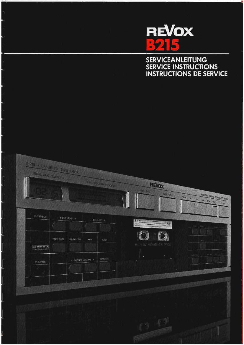
Revox B 215 Service Manual 2

Extracted text from Revox B 215 Service Manual 2 (Ocr-read)


Page 1

néVox
B215

SERVICEANLEITUNG
SERVICE INSFRUCFIONS
INSTRUCHONS DE SERVICE

Page 2

STEUJEEE REVOX 3215

Cassetten-Tunbandmaschine 9215

DEUTSCH 1 ALLGEMEINES 0-1/1
2 AUSBAU D-2/1
3 LAUFHERKEINSTELLUNGEN D-3/1
4 SCHALTUNGSBESCHREIBUNG 0-4/1
5 AUDIOEINSTELLUNGEN D-5/1
Cassette Tape Deck 8215

EN BL I SH 1 GENERAL E-Ill
2 DISASSEMBLY 5-2/1
3 TAPE TRANSPORT ADJUSTMENTS E-3/1
4 CIRCUIT DESCRIPTION E-4/1
5 AUDIO ALIGNMENTS E-5/1

Magnetnphene a cassette 13215
FRAN gA I S 1 GENERALITES F-1/1
2 DEMONTAGE F-2/1
3 REGLAGE DU MECANISME F-3/1
A DESCRIPTION DES CIRCUITS F-4/1
S REGLAGES AUDIO F-5/1
SCHEHATA LAUFHERK 6/1
6 TAPE-TRANSPORT-SCHEMATICS 6/1
SCHEMAS DE LA COMMANDE DU MECANISME 6/1
SCHEMATA AUDIO 7/1
7 AUDIO-SCHEMATICS 7/1
SCHEMAS AUDIO 7/1

Page 25

Siflu©§rsa nEVox 3215 E-a/z

I Adjust the engaged length with the adjusting screw [H] 3.1.5 Adjusting the pinch roller solenoid and the dashpot
(Fig. 3.3) in such a way that the opposite end of the
measuring slide is located in the range of the milled These adjustments should only be made when the pinch
markings roller solenoid is cold ! (room temperature)

I with the pivoting carrier engaged, Lift the pinch The pinch roller solenoid should only be shifted by
roller until. an air gap is obtained between the capstan pushing on the armature and never on the shift Leverl
shait and the pinch roller This would result in an incorrect adjustment.

I Fineadjust with screw [H] until the pinch roller is
"exactly parallel to the capstan shaft (check both I Loosen but do not compLetely turn out both mounting
rollers) screws (3 mm hexagon socket)

I After the adjustments have been made, secure the I Tighten hexagon nut on armature
adjusting screw by tightening the slotted round nut I Detach plug connections of pinch roller solenoid
(special screwdriver part No. 56161) I Apply 16.5 V to pinch roller solenoid (check polarity

because oi tree-wheeling diode)

I Loosen hexagon not on armature by 90'

I Press against hexagon nut of the armature in order to
slide the magnet to the rear stop, and fasten both
mounting screws.

I Disconnect 16.5 V from the solenoid and retighten hexa-
gon nut on the armature. The resulting air gap is now
0.18 mm

I Reapply 16.5 V test voltage: the pivoting carrier
should now move to the PLAY position.

I Remove test voltage and restore plug connections

I Alternately press PLAY and STOP keys and observe the
movement of the pivoting carrier. By turning the hexa-
gon nut [81 on the dashpot (Fig. 3.6). adjust the
damping action in such a way that the pivoting carrier
moves steadily and without jerking into the PLAY or
STOP position.

F . 3.3
\ 1
gummy» \ _
1
fl 0
| F
m .
~4\ , r 7 i
T HE) E

'1 U E r \

Fig. 3.6

Fig. 3.4

3.1.6 checking the dashpot

The dashpot should be adjusted in such a way that the
pivoting carrier (cassette inserted) moves quickly but
without excess stopping noise into the corresponding
position when the PLAY and STOP keys are pressed.

This movement should be completed within 0.5 to 0.8 5. If
the pivoting carrier blocks occasionally, the freedom of I
movement oi the dashpot [D] (Fig. 3.6) and the shaft [C]
should be checked.

The dashpot can be adjusted with screw [B]. The adjust-
ment should be made when the pinch roller solenoid is at
room temperature.

Note:

Starting with serial number 7301. a dashpot is used that
needs no adjustment. This new dashpot is automatically
shipped on corresponding parts orders.

Fig. 3.5