Revox B 203 Service Manual

This is the 158 pages manual for Revox B 203 Service Manual.
Read or download the pdf for free. If you want to contribute, please upload pdfs to audioservicemanuals.wetransfer.com.

Page: 1 / 158
Revox B 203 Service Manual

Extracted text from Revox B 203 Service Manual (Ocr-read)


Page 1

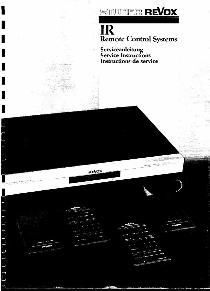
IR

Remote Control Systems

Serviceanleitung
Service Instructions
Instructions de service

A

Page 72

REVOXIRREMOTECONTBOLSVSTEMS

E 5M"

HanduheLd remote controt transmitter

ALL tape transport functiuns as ueLL ea the monitur
function or the Laasette tape recorder can be initiated
from the remote aontroLs 3201, 820160, 3nd 8205. The re-
csrder is Switnhed on when one vi the keys PAUSE, <<, >>,
PLAY 0r STQP i5 pressed, and the corresponding tunetien is
executed. The POWER switch en the unit itseLi can be in
the ON or STANDBY position. The recflrd funczinn is acti-
vated by cimuLtaneousLy pressing REC and PAUSE or REC and
PLAY. For remote cnntroL of the monitor function (changen
aver SOURCEiIAPE), the MONITOR awitch on the recorder must
be in SOURCE position. The PGHER OFF key switches off aLl
remote controlied units. wiih the h key two tape machines
can he montrolhnd independentLy of each other by addressr
ing the * funntion In one of the units.

Addreasing the * function

Open the jumprr (J3) en the IR receiver FEB 01 one of
the tune recorders Lrefer to ccmponent diagram}. As a con
sequence alt cemmands of this unit aiLL be executed onLy
when the * key ig preaaed first and held, and in additian
the corresponding function key is pressed.

5.3.2 REVflX 3:51, 3252 Tape Remote PCB

AppLicaticn:

Whan the Tape Remote PCB 1.?25.?80 is inatalléd in the
825118252 ampiifier, an npan reel recorder 87? or a
cafisette tape recorder 8710 MK! can be anntrotted via the
IR receiver of the 8251/8252.

Silk of materials:

i> TAPE REMOTE PCB

ix 9w€0nductor cable

1% TAPE REMOTE cable harness

1.725.?80
1.025.702.00
1.725.940.00

2k CabLe cLeats 35.03.0121
Ex Scr&us M3 x 3 21.26.0355
2x Nutb M3 x U.8 22.01.3030
2x PCB haLders 35.03.0130

Warning:

The TAPE REMUTE PCB 1.725.?30 contains eLectrostaticaLly
sensitive components (ESE). The carrnsponding provisions
are absotuteLy necessary fer installation.

Instaltatibn:

n Remove top Amptifier cover (unfasten tun screug).

I Push out the blankvoff cover (rear/connectorpanet, TAPE
YRANSPORT 577/3710) and instalk the 10-pin DIN aocket of
the TAPE REMOTE cabLe harness in this position (A).

9.5.10

I Insert the the PCB hotders into the smaLL hates on the
aide paneL (D) and snap the PCB (cabLe harness facing
the front panEL) into the holders (cautivn: electroshn
ticalLy 5ensitive components!>.

l PLug the smaLL cable harness into the CIS socket (E).

I Fix the two cleats in position (5) and cc) (peeL off the
plastic fiLm at the glueing pasition and press the (Leat
firmLy against the metek sheets.

I Draw the Large cabte harness (as iLLustrated in Fig.

5.15) intc the cabte clip and plug it to socket (F 0%

the TAPE REMOTE PCB.

ReinataLl top cover.

I Plug the cable 1.023.707.00 into the {APE REMGTE
877/87i0 socket of the amplifier and into the TAPE DRiVE
hecket of the open reeL vr casgette tame recorder.

Operating tips:

Yhe connected open reeL or cassette tape recorder can be
remota controlteo onLy via the 8251/8252 umpLifier.
The unit cannot be switched on or off from the IR remote
control, the power switch of the unit has to be actuated
for thia purpose. Additianat information can be found in
the operation instructions (Sectinn 2.1.2).