Realistic sta 2290 scans
This is the 4 pages manual for realistic sta 2290 scans.
Read or download the pdf for free. If you want to contribute, please upload pdfs to audioservicemanuals.wetransfer.com.
Extracted text from realistic sta 2290 scans (Ocr-read)
Page 2
10. ALIGNMENT INSTRUCTIONS
AUDIO CIRCUIT ADJUSTMENT/CHECK
EQUIPMENT REQUIRED
1. DC Voltmeter
2. Audio Oscillator
3. Oscilloscope
4. AC Voltmeter
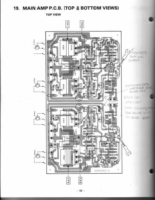
For location of connection points and trimmer resistors, see P.C.B. view.
MAIN AMP ADJUSTMENT/CHECK
NOTE: .
oMaintain voltage at 120 volts, 60 Hz AC. (UL. C.S.LI a
50 Hz for Australia 8 220/240 V AC, 50 Hz for Europe
oSet SELECTOR switch to AUX.
oSet Mode switch to Stereo.
oSee P.C.B. illustration for alignment points/adjustmns
CONNEC- AU DIO
STEP ADJUSTMENT EQUIPMENT TION FREQ. LEVEL
Check balance DC See No DC voltage
by measuring DC voltmeter Fig. 1 signal should be
1 voltage across within i 30 mV --
Output terminal
of L and R channel.
Idling current DC See NO Adjust voltage was
adjustment voltmeter Fig. 2 signal between TPI and TP2 V! I
(L chi and
2 TP3 and TP4 IR Ch)
to be 10 mV :2 mV
(8 ohm load)
For location of connection points and trimmer resistors, see P.C.B. view.
4,010+me m O'Iv:2
\ I
L our In Out) \
(T: '3) (TE) ,/7\
GROUND D T
l_.
MAIN AMP DC VOLTMETER MAIN AMP DC VOLT
[SOmV to +30mV) (SHIV N 2"
Figure 1 Figure 2
PROTECTOR CIRCUIT CHECK
STEP ADJUSTMENT EQUIPMENT CONNECTION 3:33: FREQ- SETTING LEVE.
Audio Osc. Fig. 3 1000 Hz VOLUME: Adjust ion-
AC Voltmeter max. to get W 8
1 Oscilloscope BASS, MID of 2 veils I -
8 TREBLE: load).
Center
Check if Same as Fig. 3 1000 Hz Same as No output *
protector STEP 1 STEP 1 after output
2 circuit is is shorted 7.
functioning
Check for Same equip- Fig. 3 1000 Hz Same as Normal at-
normal ment as STEP 1 output fig! 3
3 output STEP 1. driven inns
output load: at 4 ohm II
4 ohm
-32,