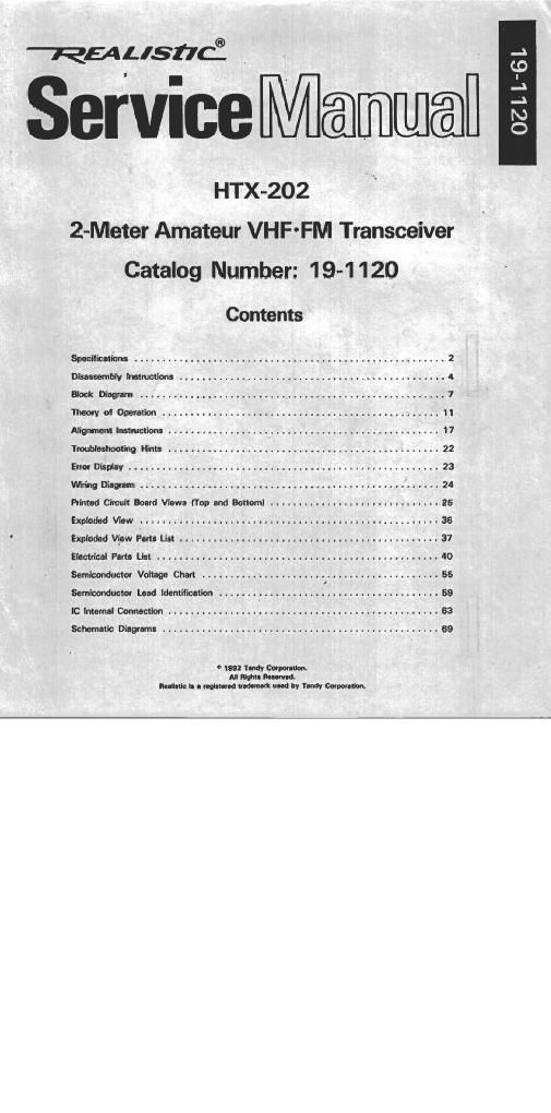
Realistic htx 202 service manual
This is the 72 pages manual for realistic htx 202 service manual.
Read or download the pdf for free. If you want to contribute, please upload pdfs to audioservicemanuals.wetransfer.com.
Extracted text from realistic htx 202 service manual (Ocr-read)
Page 1
ervice Mama
HTX-202
2-Meter Amateur VHF ~FM Transceiver
Catalog Number: 1 9-1 1 20
_\
LID
_\
-A
N
O
Contents
Specifications .................... . .................................. 2
Disassembly Instructions ............................................... 4
Block Diagram .......................... , ............................. 7
Theory ot Operation ........................................... 1 ..... 11
Alignment Instructions .................. .............................. 17
Troubleshooting Hints ................................................ 22
Error Display ....................................................... 23
Wiring Diagram . . ............................................ ...... 24
Printed Circuit Board Views (Top and Bottom! .............................. 25
Exploded View ..................................................... 36
Exploded View Parts List .............................................. 37
Electrical Parts List .................................................. 40
Semiconductor Voltage Chart ...................... , .................... 55
Semiconductor Lead Identification ....... . ............ .................... 5 9
IC Internal Connection ................................................ 63
Schematic Diagrams ................................................. 69
° I992 Tandy Corporation.
All Night. Round.
Realistic is a registered trademark used by Tandy Corporation.
Page 2
SPECIFICATIONS
General '
Transmitter .......................................... PLL synthesizer, Frequency Modulation
Receiver .................. . PLL synthesizer. superheterodyne system
Communication Frequency Range ................................................ I44~I4BMH1 (SKHz step)
Operating Voltage ................................................................. 6~ 14V DC (negative groundl
Temperature and Humidity range ............... 14°F~ 140°F (-10°C~ +60°Cl and 10%~90%
Transmitter/Receiver switching ............................................................................ Electrical
Standard Test Conditions
Battery supply voltage . . 7.2V DC
Modulation ...................................... SIG-ll
Receiver output Impedance ...................................... 8 ohms, nonainductive .
ANT. load impedance of transmitter ........... 50 ohms, non-inductive
Ambient conditions:
Temperature . 63°F ~ 91°F (17": ~33°Cl
Humidity ...........................
Receiver
Description Nominal Limit
Intermediate Frequency
lst IF .. 21.4MHz
2nd IF .......................................................... 455 KHz
Sensitivity:
12 d8 SINAD ............ _. ........................................ 0.2,.v 0.25,.v
20 do No. ......................................................... 0.35pv 0.4,.v
Squelch Sensitivity:
Threshold .......................................................... 0.1pV 0.2uV
Tight ................... t ...................... 4- luv
Spurious Response Attenuation .......... 6MB
Intermodulation Attenuation .............. 60GB
Adjacent Channel Rejection (25KHzl 6MB
Modulation Acceptance Bandwidth ..... .. 7.5KHz
Hum and Noise ..................................................... 50dB 40dB
Audio Output Power (10% THDI:
7.2V DC ..................................... 0.25W
9V DC ..................... . ............ CLAW
0.7W
Audio Distortion 2% ' 10%
Audio Response . ............. -6dB/oct + II ads, Gdaloct
Current Drain:
Standhby without Power Save .............................. 35mA 45mA
Stand-by Powar Save 25mA 30mA
CTCSS Sensitivity .. 0.15uV 0.2uV
DTMF Squelch Sensitivity ................................. . ..... 0.2pV 0.25av