QSC usa 400 pwr sm
This is the 2 pages manual for QSC usa 400 pwr sm.
Read or download the pdf for free. If you want to contribute, please upload pdfs to audioservicemanuals.wetransfer.com.
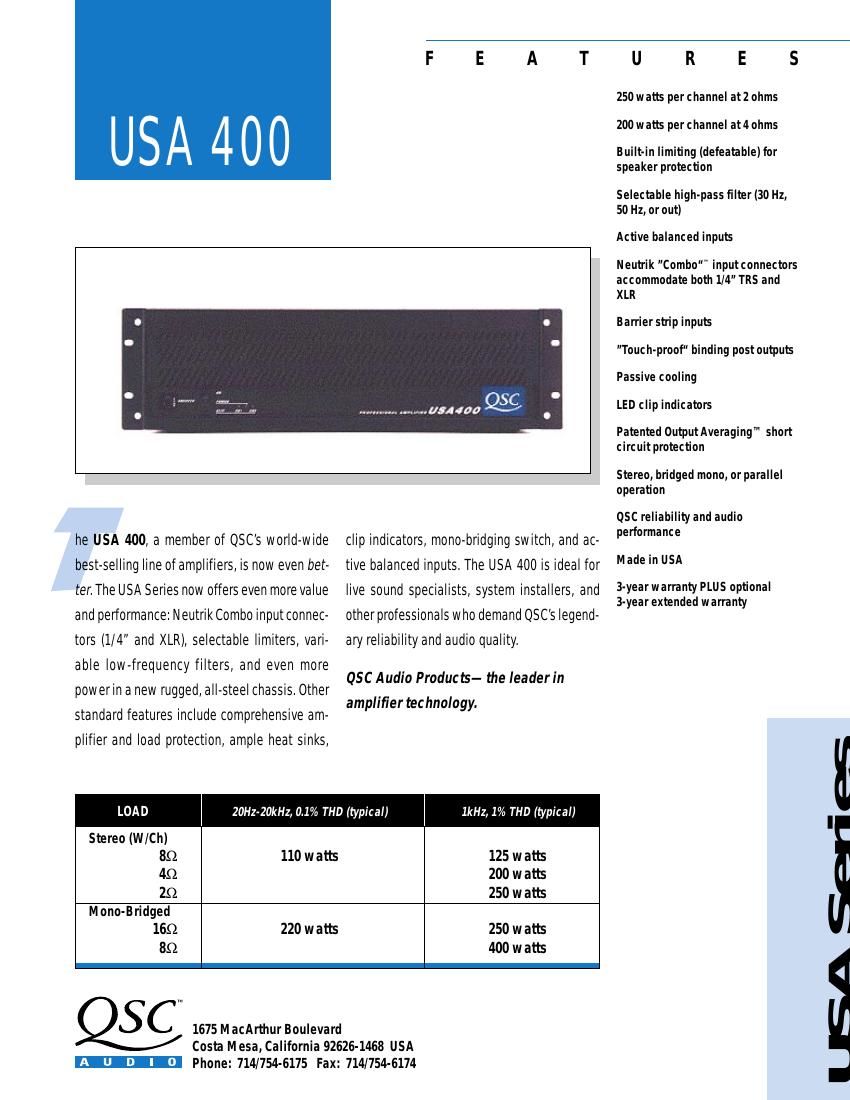
Extracted text from QSC usa 400 pwr sm (Ocr-read)
Page 1
ARCHITECTÕS AND ENGINEERÕS SPECIFICATIONS The power amplifier shall contain all solid-state circuitry, using complementary silicon semiconductors. The amplifier shall operate from 50-60 Hz AC power, with voltages of 100, 120, or 240 Vac. The amplifier shall operate from a normal household AC outlet, drawing less than 900 VA when driven with random program material at 1/8 rated power into four ohm loads. The amplifier shall be supplied with a single molded AC cord having an appropriate AC plug for the intended operating voltage. The amplifier shall contain two independent channels. Each chan- nel shall have independent protective circuitry against open cir- cuit, short circuit, or reactive loads, and the remaining channel shall continue to operate if one channel fails. A muting circuit shall provide three seconds of muting after turn-on, and shall mute within 1/4 second after turn-off or loss of power, to protect the load against turn-on or turn-off thumps. Self resetting ther- mal shutdown shall protect the circuitry against temperatures in excess of 90°C, and a front panel resettable circuit breaker or fuse shall protect against AC overloads. Each channel of the amplifier shall have an independently defeatable limiter. Each channel shall also have bypassable high- pass filtering, with independently selectable -3 dB frequencies of 30 Hz or 50Hz. The limiter and high pass filter controls shall be on an 8-position DIP switch on the amplifierÕs rear panel. Each channel of the amplifier shall typically be capable of meet- ing the following performance criteria, with both channels driven simultaneously, unless otherwise stated: Output power, 8 ohms per channel, 20 Hz-20 kHz, less than 0.1% distortion, at least 110 watts rms per channel. Output power, 4 ohms per channel, 1 kHz, less than 1% distortion, at least 200 watts rms per channel. Frequency response shall be 20 Hz-20 kHz + 0, - 1 dB at 1 watt output. SMPTE IM distortion shall be less than 0.025% at rated power, 8 ohms, and less than 0.05% at rated power, 4 ohms. IHF damping factor shall be at least 200. Signal to noise, below rated output, shall be at least 105 dB (A weighted). Dynamic head- room at 8 ohms shall be at least 2 dB. The voltage gain shall be 29 dB at full gain. The input sensitivity for rated 8 ohm power shall be 1.12 Vrms. Input impedance shall be 20 kilohms bal- anced and unbalanced noninverting, 10 kilohms unbalanced in- verting. Balanced, bridging input circuit shall be standard, and the amplifier shall meet all performance criteria in the balanced or unbalanced mode. The amplifier shall have passive cooling for ultra-quiet operation. Each channel shall have the following controls, indicators, and connectors: Rear mounted gain control calibrated in dB. Clipping indicator, responding proportionally to any distortion in excess of 0.1%. Balanced/unbalanced input jack of the Neutrik "Combo" (combined 1/4" TRS and XLR). Bal- anced input of the barrier strip screw terminal type. Speaker ter- minals of the "touch proof" binding post type. In addition, the chassis shall feature a rear mounted mono-bridging switch, front mounted AC switch and circuit breaker or fuse in some export locations, mounting positions on the rear for optional 70 V out- put transformers, and built-in rack mounting ears. The chassis shall mount in a 19" rack, occupying 3 rack spaces (5.25"). Chas- sis depth behind the rails shall be 8.5" plus 1 in allowance for the binding posts. Weight shall be 24 Ib. The amplifier shall be the QSC Model USA 400. BACK USA 400 Specifications OUTPUT POWER (per channel, typical) 8 ohms, 20 Hz to 20 kHz, 0.1% THD, 110 watts 8 ohms, 1kHz, 1% THD, 125 watts 4 ohms, 1 kHz, 1% THD, 200 watts 2 ohms, 1 kHz, 1% THD, 250 watts OUTPUT POWER (bridged mono) 16 ohms, 1 kHz, 1% THD, 250 watts 8 ohms, 1 kHz, 1% THD 400 watts DISTORTION: SMPTE-IM, less than 0.025% FREQUENCY RESPONSE: 20 Hz to 20 kHz, +0/-1 dB, 1 watt DAMPING FACTOR: Greater than 200 DYNAMIC HEADROOM: 2 dB at 8 ohms NOISE: 105 dB below rated output (A weighted) SENSITIVITY: 1.12 Vrms for rated power (8 ohms) VOLTAGE GAIN: 28 (29 dB) INPUT IMPEDANCE: 10K unbalanced, 20K balanced CONTROLS: Front: AC Switch, AC Circuit Breaker Back: Stereo/Bridge Switch/Ch 1 and Ch 2 Gain Knobs 8 Position DIP Switch for Filter & Limiter INDICATORS: PWR-ON: Green LED CLIP: Red LED, 1 per channel CONNECTORS: (each channel) Input: Barrier strip and Neutrik "Combo" 1/4" TRS and XLR, tip positive Speakers: "Touch proof" binding posts COOLING: Passive AMPLIFIER PROTECTION: Full short circuit , open circuit, ultrasonic, and RF protection. Stable into reactive or mismatched loads. LOAD PROTECTION: On/off muting and DC-fault protection. OUTPUT CIRCUIT TYPE: Complementary linear outputs. POWER REQUIREMENTS: 100,120, 240 Vac, 50-60 Hz POWER CONSUMPTION: Normal Operation: 4 ohms per channel: less than 4.4 amps, 120 Vac (900 VA) DIMENSIONS:19.0" (48.3 cm) rack mounting 5.25" (13.3 cm) tall (3 spaces) 9.5" (24.1 cm) deep WEIGHT: 24 Ibs (10.9 kg) net, 28 Ibs (12.7 kg) shipping Output Averaging ª short circuit protection (US Patent 4,321,554) SPECIFICATIONS SUBJECT TO CHANGE WITHOUT NOTICE. 1675 MacArthur Boulevard Costa Mesa, California 92626-1468 USA Phone: 714/754-6175 Fax: 714/754-6174