Pioneer xvdv 8 schematic
This is the 5 pages manual for pioneer xvdv 8 schematic.
Read or download the pdf for free. If you want to contribute, please upload pdfs to audioservicemanuals.wetransfer.com.
Extracted text from pioneer xvdv 8 schematic (Ocr-read)
Page 1
Pioneer sound. I/ILS/bn.sou/
Service
Manual
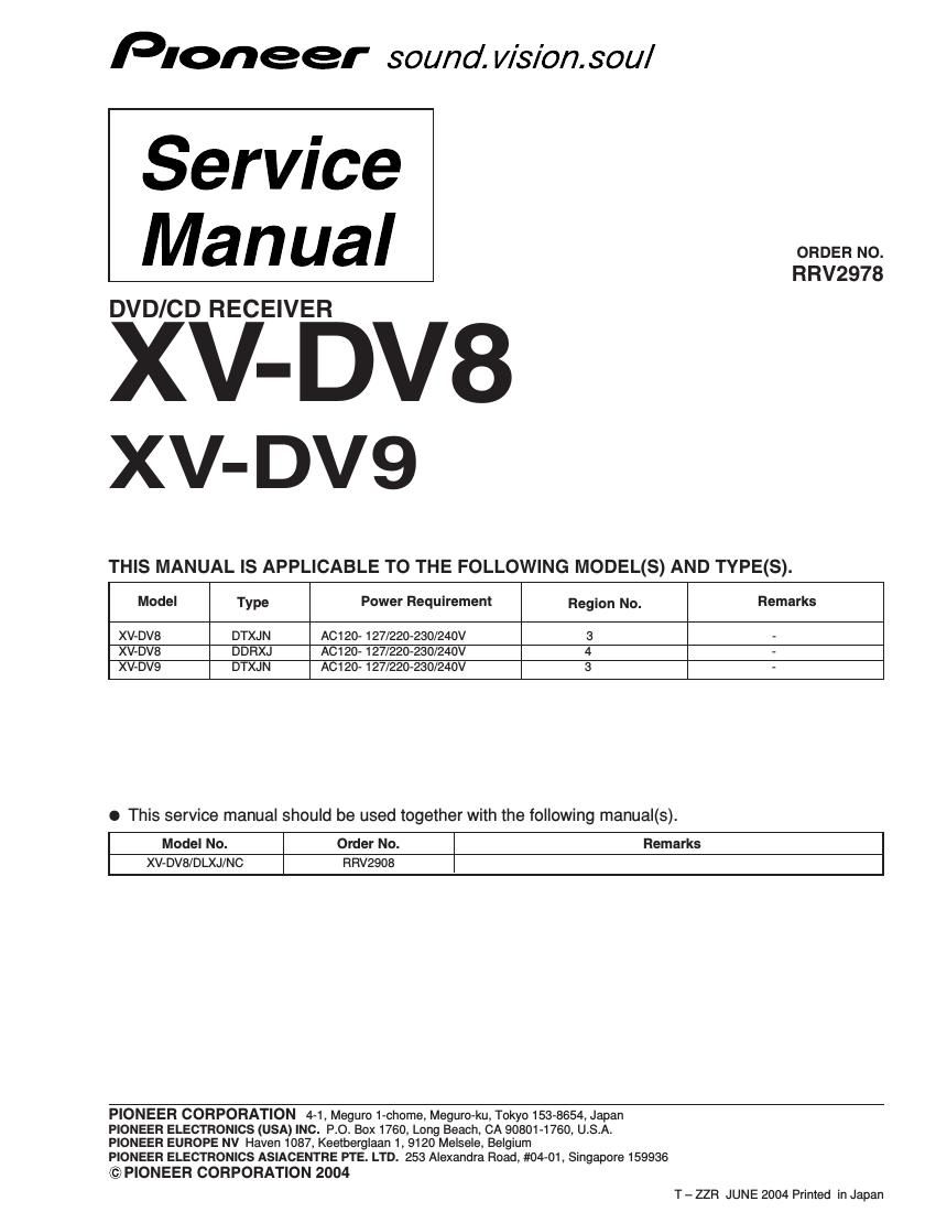
DVD/CD RECEIVER
XV- DV8
XV- DV9
THIS MANUAL IS APPLICABLE TO THE FOLLOWING MODEL(S) AND TYPE(S).
ORDER NO.
RRV2978
Model Type Power Requirement Region No. Remarks
XV-DV8 DTXJN AC120- 127/220-230/24OV 3 -
XV-DV8 DDRXJ AC120- 127/220-230/24OV 4 -
XV-DVQ DTXJN AC120- 127/220-230/24OV 3 -
o This service manual should be used together with the following manual(s).
Model No.
Order No.
Remarks
XV- DV8/DLXJ/NC
RRVZQOB
PIONEER CORPORATION 4-1, Meguro 1-chome, Meguro-ku, Tokyo 153-8654, Japan
PIONEER ELECTRONICS (USA) INC. P.O. BOX 1760, Long Beach, CA 90801-1760, U.S.A.
PIONEER EUROPE NV Haven 1087, Keetberglaan 1, 9120 Melsele, Belgium
PIONEER ELECTRONICS ASIACENTRE PTE. LTD. 253 Alexandra Road, #04-01, Singapore 159936
©PIONEER CORPORATION 2004
T - ZZFl JUNE 2004 Printed in Japan
Page 2
1. CONTRAST OF MISCELLANEOUS PARTS
NOTES: 0 Parts marked by NSF are generally unavailable because they are not in our Master Spare Parts List.
0 The /
i\\
Therefore, when replacing, be sure to use parts of identical designation.
0 Screws adjacent to V mark on product are used for disassembly.
O For the applying amount aflubricants or glue, follow the instructions in this manual.
(In the case of no amount instructions, apply as you think it appropriate.)
0 Reference Nos. indicate the pages and Nos. in the service manual for the base model.
C When ordering resistors, first convert resistance values into code form as shown in the following examples.
EL] When there are 2 eflective digits (any digit apartfrom 0), such as 560 ohm and 47k ohm (tolerance is shown by J=5%,
E142 When there are 3 eflective digt
andK=10%).
560 a 56 X 101 a
47k a 47X 105 -
0.5 4 R50
1 A 1R0
(such as in high prec ion metalfilm re.
mark found on some component parts indicates the importance of the safety factor of the part.
- 2
XV- DV8
-
3
5.62k A 562 x 10 a 5621 -------------------------------------------------------- RN1/4PCI IF
I CONTRAST 0F TABLE
XV-DV8/DLXJ/NC, DTXJN, DDRXJ and XV-DV9/DTXJN are constructed the same except for the following:
Ref _ _ Part No.
' Mark Symbol and Description Remarks
No. XV-DV8 XV-DV8 XV-DV8 XV-DV9
IDLXJ/NC /DTXJN IDDRXJ IDTXJN
NSP MAIN ASSY XWM3232 XWM3232 XWM3232 XWM3235
P9- 3 AF ASSY XWZ3836 XWZ3836 XWZ3836 XW23839
P7- 1 A AC Power Cord ADG1154 ADG1154 ADG1158 ADG1154
P7- 3 Remote Control Unit XXD3080 XXD3080 XXD3080 XXD3081
P7- 6 FM Antenna Assy ADH7030 ADH7034 ADH7030 ADH7034
P7- 8 Operating Instructions (English) XRB3033 Not used XRCS125 Not used
P7- 9 Operating Instructions XRC3125 XRC3122 XRC3124 XRC3129
(Chinese) (Thai) (Spanish) (Thai)
P7-1 5 Packing Case XHD3424 XHD3422 XHD3420 XHD3423
A AC Power Cord Not used Not used XDG3009 Not used No. 1
A Power Plug Adapter Not used Not used XKM3002 Not used No. 2
Caution Sheet AR Not used Not used XRH3002 Not used No. 3
P9-21 NSP Chassis (MTL) XNA3020 XAN3021 XNA3020 XNA3021
P9-22 Rear Panel (HTL) XNC3275 XNC3277 XNC3272 XNC3293
P9-24 Mecha Frame (HTL) XNG3121 XNG3127 XNG3121 XNG3127
P9-30 Fan Cover (HTL) AMR7451 AMR7474 AMR7451 AMR7474
P9-35 Rotary Tray VNK5558 VN K5561 VN K5558 VNK5561
P9-38 PCB Holder XMR3087 XMR3090 XMR3087 XMR3090
P9-39 NSP Tray Cap Assy XXG3174 XXG3198 XXG3174 XXG3198
P11- 5 NSP Front Panel Assy XXG3177 XXG3196 XXG3177 XXG3197
P11- 7 Display Window XAK3447 XAK3447 XAK3447 XAK3466
P11-19 MIC knob XAA3024 XAA3025 XAA3024 XAA3025
Notes :+The numbers in the remarks column correspond to the numbers on the EXPLODED VIEWS .
+ For PCB ASSEMBLIES, Refer to CONTRAST OF PCB ASSEMBLIES and 2. SCHEMATIC DIAGRAM.
2