Pioneer xsp 650 service manual

This is the 19 pages manual for pioneer xsp 650 service manual.
Read or download the pdf for free. If you want to contribute, please upload pdfs to audioservicemanuals.wetransfer.com.

Page: 1 / 19
pioneer xsp 650 service manual

Extracted text from pioneer xsp 650 service manual (Ocr-read)


Page 1

GD PIONEER

The Art of Entertainment

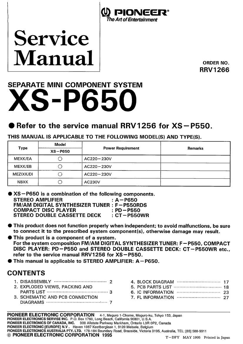
Service
Manual

RRV1266

SEPARATE MINI COMPONENT SYSTEM

XS-P650

0 Refer tO the service manual RRV1256 for XS-P550.
THIS MANUAL Is APPLICABLE TO THE FOLLOWING MOOELISI AND TYPEIS).

Model
Type Power Requirement Remarks
XS - P650
MEXK/EA O A0220-230V
MEXK/EB O A0220-230V
MEZIXK/DI O AC220-23OV
NBXK 0 AC 230V

O XS-P650 is a combination of the following components.

STEREO AMPLIFIER : A-P650
FM/AM DIGITAL SYNTHESIZER TUNER : F-P550RDS
COMPACT DISC PLAYER : PD-P550

STEREO DOUBLE CASSETTE DECK : CT-P550WR

O This product does not function properly when independent; to avoid malfunctions, be sure
to connect it to the prescribed system componenfls), otherwise damage may result.

0 This product is a component of a system.
For the system composition FM/AM DIGITAL SYNTHESIZER TUNER: F- P550. COMPACT
DISC PLAYER: PD-P550 and STEREO DOUBLE CASSETTE DECK: CT-P55OWR etc.,
refer to the service manual RRV1256 for XS-P550.

O This manual is applicable to STEREO AMPLIFIER: A-P650.


CONTENTS
1. DISASSEMBLY ------------------------------------ 2 4_ BLOCK DIAGRAM .............................. 17
2. EXPLODED VIEWS, PACKING AND 5. PCB PARTS LIST ---------------------- 18
PARTS LIST .......................................... 3 5' IC INFORMATION .............. 23
3. SCHEMATIC AND PCB CONNECTION 7. FL INFORMATION ----------------------------- 27
DIAGRAMS .......................................... 7

PIONEER ELECTRONIC CORPORATION 4<1.Meguro1-Chome, Meguro-ku, Tokyo 153. Japan

PIONEER ELECTRONICS SERVISE INC. PO. Box 1760, Long Beach. California 90801, USA.

PIONEER ELECTRONICS OF CANADA, INC. 300 Allstate Parkway Markham, Ontario LSR 0P2, Canada

PIONEER ELECTRONIC [EUROPE] N.V. Haven 1087 Keelberglaan 1. 9120 Meisele, Belgium

PIONEER ELECTRONICS AUSTRALIA PTV. LTD. 178484 Boundary Road, Braeside. Victoria 3195, Australia. TEL: [03] 580-9911

@ PIONEER ELECTRONIC CORPORATION 1995 T_DFY MAY 1995 Prmtedmkm

Page 2

XS-P65O

1. DISASSEMBLY (A- P650)

0 Removal of the Front Panel

1.
2.

02

Remove the bonnet.

Remove the volume knob.

(Please be careful, as the STA. LENS is in the volume
knob.)

. Remove the screw (D holding the SFC assy.
. Remove the left and right screw (2) (each one) fixing the

front panel to chassis.

. Remove the three screws,® at the lower side of the front

panel.

. Disengage the left and the right hook of the front panel

(refer to figure) and the hook at the lower part, and then
remove the front panel from the chassis.


Front Panel

0 Removal of the Fan Motor

Remove the bonnet.

Remove the screw @ of the rear panel.
Remove the screw (5) of the connector.

. Remove the screw © of the SP OUT terminal.
i Remove the screw (7) of the pin jack.

. Remove the rear panel from the chassis.

. Remove the screw of the fan motor.

NOWOIJ-xgngat-I

Screw @r

Rear Panel / Screw©
_ Wrew 3)

Screw

Screw ®