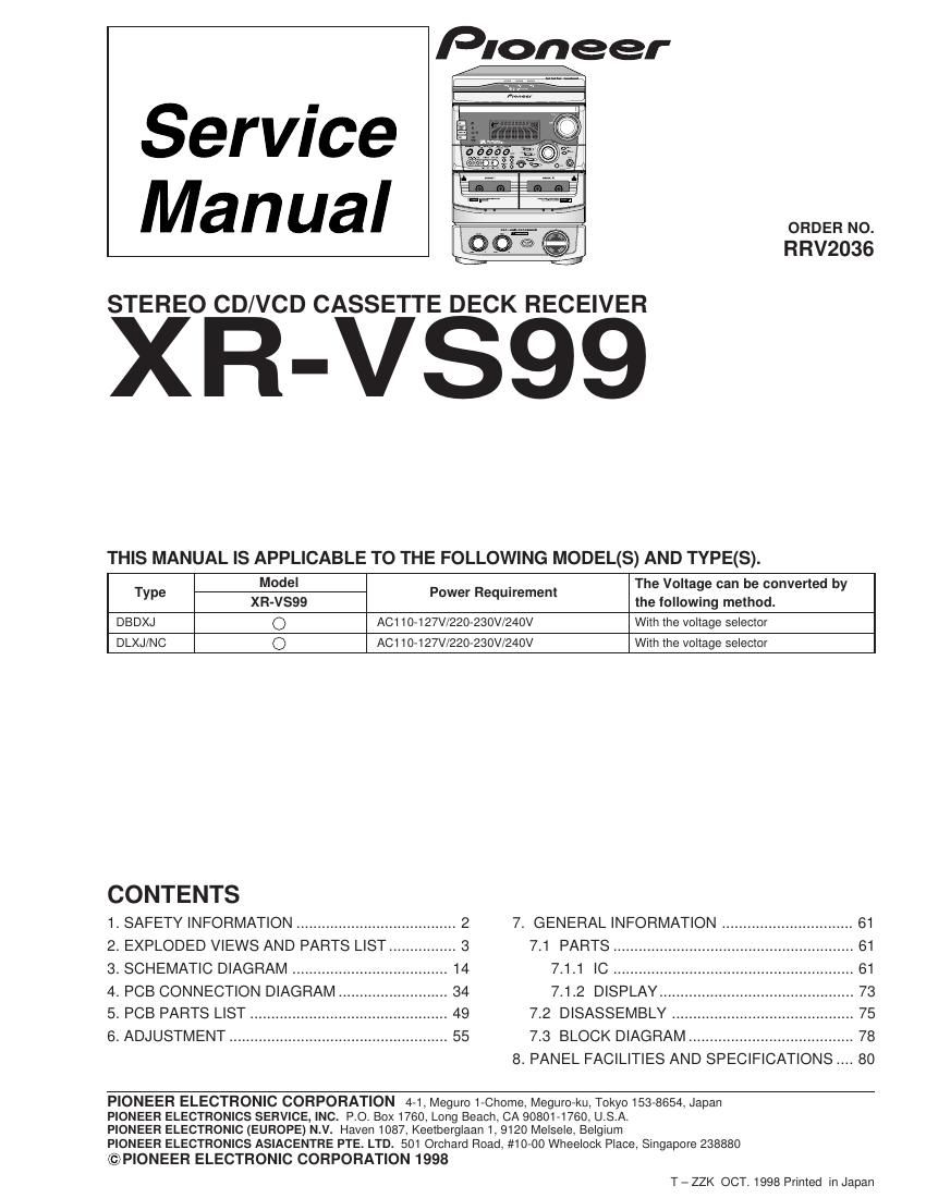
Pioneer xrvs 99 service manual
This is the 84 pages manual for pioneer xrvs 99 service manual.
Read or download the pdf for free. If you want to contribute, please upload pdfs to audioservicemanuals.wetransfer.com.
Extracted text from pioneer xrvs 99 service manual (Ocr-read)
Page 1
2 XR-VS99 Printed on the Rear Panel LABEL CHECK (For DLXJ/NC type) Additional Laser Caution 1. Laser Interlock Mechanism The position of the switch (S8501) for detecting loading state is detected by the system microprocessor, and the design prevents laser diode oscillation when the switch (S8501) is pressed physically. Thus, the interlock will no longer function if the switch (S8501) is released physically and deliberatery. The interlock also does not function in the test mode *. Laser diode oscillation will continue, if pin 62 of LA9240ML (IC8101) on the CD ASSY mounted on the $M Loading Mechanism assembly is connected to GND, or else the terminals of Q8101 are shorted to each other (fault condition). 2. When the cover is opened, close viewing of the objective lens with the naked eye will cause exposure to a Class 1 laser beam. * : Refer to page 60. 1. SAFETY INFORMATION This service manual is intended for qualified service technicians ; it is not meant for the casual do-it- yourselfer. Qualified technicians have the necessary test equipment and tools, and have been trained to properly and safely repair complex products such as those covered by this manual. Improperly performed repairs can adversely affect the safety and reliability of the product and may void the warranty. If you are not qualified to perform the repair of this product properly and safely, you should not risk trying to do so and refer the repair to a qualified service technician. IMPORTANT THIS PIONEER APPARATUS CONTAINS LASER OF CLASS 1. SERVICING OPERATION OF THE APPARATUS SHOULD BE DONE BY A SPECIALLY INSTRUCTED PERSON. LASER DIODE CHARACTERISTICS MAXIMUM OUTPUT POWER: 1.3 mW WAVELENGTH: 790 nm ± 25 nm
Page 2
3 XR-VS99 2.1 PACKING 1 FM Antenna ADH7004 2 Operating Instructions XRE3019 (English/Chinese) 3 AM Loop Antenna XTB3001 4 Remote Control Unit XZN3010 (CU-XR052) 5 Battery Cover AZA7204 NSP 6 Dry Cell Battery (R6P, AA) VEM-013 7 Polyethylene Bag Z21-038 (0.03 ´ 230 ´ 340) 8 Front Pad XHA3005 (1) PACKING PARTS LIST Mark No. Description Part No. 2. EXPLODED VIEWS AND PARTS LIST NOTES: · Parts marked by "NSP" and can not be supplied. · The mark found on some component parts indicates the importance of the safety factor of the part. Therefore, when replacing, be sure to use parts of identical designation. · Screws adjacent to mark on the product are used for disassembly. 9 Rear Pad XHA3006 10 Packing Case See Contrast table (2) 11 Packing Sheet AHG7049 12 ¥ ¥ ¥ ¥ ¥ 13 Power Cord See Contrast table (2) NSP 14 Polyethylene Bag AHG7033 15 Operating Instructions XRE3018 16 Video Cord VDE1034 NSP 17 Caution Card XAX3130 NSP 18 Door Spacer XHG3002 Mark No. Description Part No. (2) CONTRAST TABLE XR-VS99/DBDXJ and DLXJ/NC are constructed the same except for the following : Mark No. Symbol and DescriptionPart No. Remarks XR-VS99 XR-VS99 /DBDXJ /DLXJ/NC 10 Packing Case XHD3055 XHD303813 Power Cord ADG1158 ADG1154 VOLKARAOKE SFCDISCDISC DISCCLEARSTATIONREMOTE CONTROL UNIT CU-XR025 MONOBAND PGMR E P E A TR A N D O MAUX P.BASS DISPLAYS L E E PPOWER 6 16 1 3 79(1/2) 8(1/2) 8(2/2)9(2/2) 10 2 13 14 1115 4 5 1817