Pioneer xrvs 500 d service manual

This is the 7 pages manual for pioneer xrvs 500 d service manual.
Read or download the pdf for free. If you want to contribute, please upload pdfs to audioservicemanuals.wetransfer.com.

Page: 1 / 7
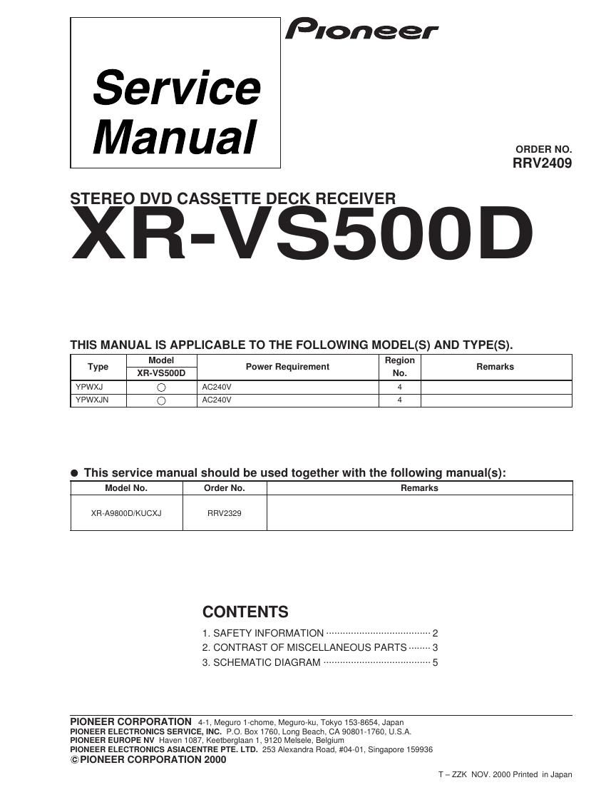
pioneer xrvs 500 d service manual

Extracted text from pioneer xrvs 500 d service manual (Ocr-read)


Page 1

XR-VS500D 2 1. SAFETY INFORMATION Printed on the Rear Panel LABEL CHECK LASER DIODE CHARACTERISTICS FOR DVD : MAXIMUM OUTPUT POWER : 5 mW WAVELENGTH : 655 nm FOR CD : MAXIMUM OUTPUT POWER : 5mW WAVELENGTH : 785 nm Additional Laser Caution 1. Inside detection switch (S201 on the SMEB assy) and loading- status detection switch (S9503 on the MOTOR assy) are detected by the microprocessor (IC11 in the DVDM assy). ¥ To permit the laser diode to oscillate, it is required to set the inside detection switch for the inside position (S201 : ON) and to set the loading-status detection switch for the clamp position (the center terminal of S9503 is shorted to +5V). The 655 nm laser diode for DVD oscillation will continue if pin 19 of IC1 is shorted to +5V (fault condition) in the DVDM assy. The 785 nm laser diode for CD oscillates if pin 20 of IC1 is shorted to +5V in the DVDM assy. In the test mode * , the laser diode oscillates when microproces- sor detects a PLAY signal, or when the PLAY key is pressed (S5931 ON in the DISPLAY assy), with the above requirements satisfied. 2. When the cover is open, close viewing through the objective lens with the naked eye will cause exposure to the laser beam. * : Refer to page 82 on the service manual RRV2329. WARNING ! THE AEL (ACCESSIBLE EMISSION LEVEL) OF THE LASER POWER OUTPUT IS LESS THAN CLASS 1 BUT THE LASER COMPONENT IS CAPABLE OF EMITTING RADIATION EXCEEDING THE LIMIT FOR CLASS 1. A SPECIALLY INSTRUCTED PERSON SHOULD DO SERVICING OPERATION OF THE APPARATUS. This service manual is intended for qualified service technicians ; it is not meant for the casual do-it- yourselfer. Qualified technicians have the necessary test equipment and tools, and have been trained to properly and safely repair complex products such as those covered by this manual. Improperly performed repairs can adversely affect the safety and reliability of the product and may void the warranty. If you are not qualified to perform the repair of this product properly and safely, you should not risk trying to do so and refer the repair to a qualified service technician.

Page 2

XR-VS500D 3 2. CONTRAST OF MISCELLANEOUS PARTS Parts marked by "NSP" are generally unavailable because they are not in our Master Spare Parts List. The mark found on some component parts indicates the importance of the safety factor of the part. Therefore, when replacing, be sure to use parts of identical designation. Screws adjacent to mark on product are used for disassembly. Reference Nos. indicate the pages and Nos. in the service manual for the base model. NOTES: When ordering resistors, first convert resistance values into code form as shown in the following examples. Ex.1 When there are 2 effective digits (any digit apart from 0), such as 560 ohm and 47k ohm (tolerance is shown by J=5%, and K=10%). Ex.2 When there are 3 effective digits (such as in high precision metal film resistors). 561 473 R50 1R0 5621 560 47k 0.5 1RD1/4PU J RD1/4PU J RN2H K RS1P K 56 x 10 1 47 x 10 3 R50 1R0561 473 5.62k RN1/4PC F562 x 10 1 5621 CONTRAST TABLE XR-VS500D/YPWXJ, YPWXJN and XR-A9800D/KUCXJ are constructed the same except for the following : Part No. Ref. No. Mark Symbol and Description XR-A9800D XR-VS500D XR-VS500D Remarks /KUCXJ /YPWXJ /YPWXJN PCB ASSEMBLIES MAIN ASSY XWM3174 XWM3173 XWM3173 P5- 1 AF ASSY XWZ3330 XWZ3327 XWZ3327 COMPLEX ASSY XWM3178 XWM3177 XWM3177 P5- 4 PRIMARY ASSY XWZ3332 XWZ3329 XWZ3329 P7- 1 DISPLAY ASSY XWZ3331 XWZ3328 XWZ3328 PACKING SECTION P3- 1 Power Cord ADG7022 ADG1160 ADG1160 P3-11 Packing Case XHD3144 XHD3140 XHD3168 P3-12 NSP Warranty Card ARY7045 ARY7027 ARY7027 NSP Polyethylene Bag Not used AHG7033 AHG7033 For Power Cord Carton Spacer Not used Not used XHB3007 For Packing EXTERIOR SECTION P5-12Power Transformer (T1) (AC120V) XTS3042 Not used Not used P5-12Power Transformer (T1) Not used XTS3038 XTS3038 (AC110-127V/220-230V/240V) P5-13 Fuse (FU1 : 6.3A) REK1085 Not used Not used P5-13Fuse (FU1 : T5A) Not used AEK1061 AEK1061 P5-25 Rear Panel XNC3065 XNC3068 XNC3068 P5-26 SEC Holder XMR3032 XMR3032 XMR3035 P5-38 Tray Cap XAK3157 XAK3157 XAK3210 P5-41 NSP Fuse Card AAX2374 Not used Not used P5-42 NSP Getter XAX3175 XAX3177 XAX3177 P5-43 65 Label ARW7050 Not used Not used NSP Name Label Not used XAL3051 XAL3051*1 NSP Name Label Not used Not used XAL3069*1 Caution Label Not used PRW1018 PRW1018*2 FRONT PANEL SECTION P7-19 JOG Knob XAA3015 XAA3015 XAA3019 P7-21 FUNC Button L XAD3061 XAD3061 XAD3089 P7-22 FUNC Button R XAD3051 XAD3051 XAD3090 P7-23 FUNC Frame L XAD3052 XAD3052 XAD3091 P7-24 FUNC Frame R XAD3053 XAD3053 XAD3092 P7-25 DV ENT Button XAD3056 XAD3056 XAD3085 P7-26 Display Panel XAK3135 XAK3136 XAK3207 P7-33 FL Cover XAK3164 XAK3163 XAK3163 P7-42 Sub Panel XAK3203 XAK3203 XAK3209 P7-50 DV Button L XAD3057 XAD3057 XAD3086 P7-51 DV Button R XAD3059 XAD3059 XAD3088 P7-52 NSP Front Panel Assy XXG3066 XXG3066 XXG3069 Notes : For PCB ASSEMBLIES, Refer to ÒCONTRAST OF PCB ASSEMBLIESÓ and Ò3. SCHEMATIC DIAGRAMÓ. *1 Stick Name Label on the Rear Panel. *2 Refer to ÒLABEL CHECKÓ.