Pioneer xra 790 service manual

This is the 24 pages manual for pioneer xra 790 service manual.
Read or download the pdf for free. If you want to contribute, please upload pdfs to audioservicemanuals.wetransfer.com.

Page: 1 / 24
pioneer xra 790 service manual

Extracted text from pioneer xra 790 service manual (Ocr-read)


Page 1

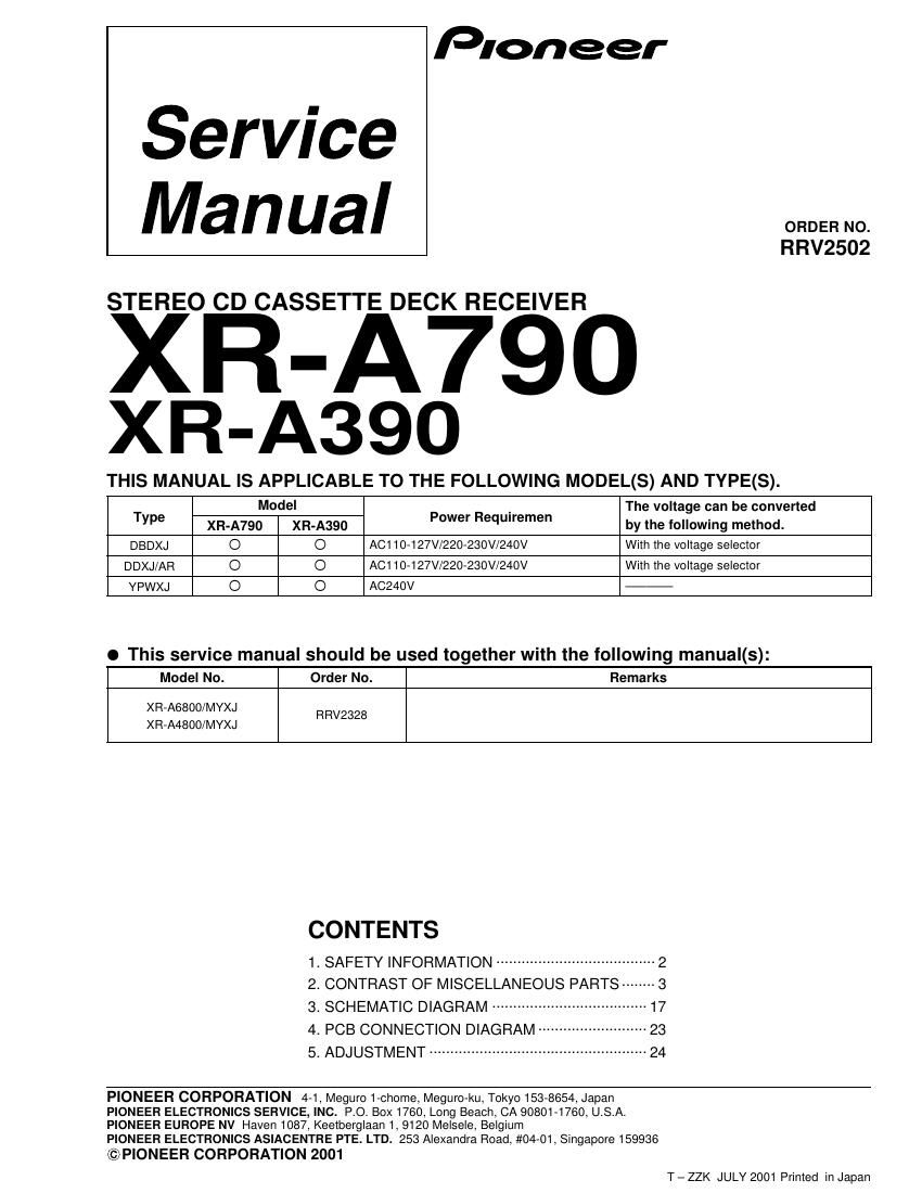
Service
Manual

Pioneer

ORDER NO.
RRV2502

STEREO CD CASSETTE DECK RECEIVER

XR-A790
XR-A390

THIS MANUAL IS APPLICABLE TO THE FOLLOWING MODEL(S) AND TYPE(S).

Type Model Power Requiremen The voltage ean be converted
XR-A790 XFl-A39O by the lollowmg method.
DBDXJ O O A0110-127V/220-230w240v With the voltage selector
DDXJ/AR O O AC1 10-127V/220-230V/240V With the voltage selector
YPWXJ O O A0240v

I This service manual should be used together with the following manual(s):

4. PCB CONNECTION DIAGRAM ------
5. ADJUSTMENT -----

Model No. Order No. Remarks
XFl-A6800/MYXJ RRV2328
XFl-A4800/MYXJ
CONTENTS
1- SAFETY INFORMATION ...................................... 2
2. CONTRAST OF MISCELLANEOUS PARTS -------- 3
3- SCHEMATIC D'AGRAM ..................................... 17


PIONEER CORPORATION 4-1, Meguro 1-chome, Meguro-ku, Tokyo 153-8654, Japan
PIONEER ELECTRONICS SERVICE, INC. P.O. BOX 1760, Long Beach, CA 90801-1760, U.S.A.
PIONEER EUROPE NV Haven 1087, Keetberglaan 1, 9120 Melsele, Belgium

PIONEER ELECTRONICS ASIACENTRE PTE. LTD. 253 Alexandra Road, #04-01, Singapore 159936

© PIONEER CORPORATION 2001

T - ZZK JULY 2001 Printed in Japan

Page 2

XR-A790, XR-A390

1. SAFETY INFORMATION

LABEL CHECK

Printed on the Rear Panel
(Except XR-A390/DBDXJ)

CLASS I
LASER PRODUCT

TO BEAM

DDXJ/AR TYPE

CAUTTDN :wmmmmwummm.mmmm
.WWWW WW
WRSCHT ' Wme M
,mmoammumwm WWW
ADVARSEL . W 5'

VARNING :memwmmwummummmu

WW), .Awmummummumva mu
mlawssss
CMDADD .Wmmsmummmmu
14m
mm

DBDXJ and YPWXJ TYPES

CAUTION
INVISIBLE LASER
RADIATION WHEN OPEN,
AVOID EXPOSURE

PRWIOIS

IMPORTANT
THIS PIONEER APPARATUS CONTAINS
LASER OF CLASS 1.
SERVICING OPERATION OF THE APPARATUS
SHOULD BE DONE BY A SPECIALLY
INSTRUCTED PERSON.

LASER DIODE CHARACTERISTICS 7
MAXIMUM OUTPUT POWER: 5 mW
WAVELENGTH1780 . 785 nm

Additional Laser Caution

. Laser Interlock Mechanism

The position of the switch (89501) for detecting loading
state is detected by the system microprocessor, and
the design prevents laser diode oscillation when the
switch (89501) is pressed physically.

Thus, the interlock will no Iongerfunction ifthe switch (89501)
is released physically and deliberatery.

The interlock also does not function in the test mode *.
Laser diode oscillation will continue, if pin 1 of
CXA1821 M (ICB101) on the CD ASSY mounted on the
SM Loading Mechanism assembly is connected to GND,
or else the terminals of 08101 are shorted to each other
(fault condition).

2. When the cover is opened, close viewing of the objective
lens with the naked eye will cause exposure to a Class
1 laser beam.

* : Refer to page 61 on the service manual RRV2328.