Pioneer xra 780 service manual
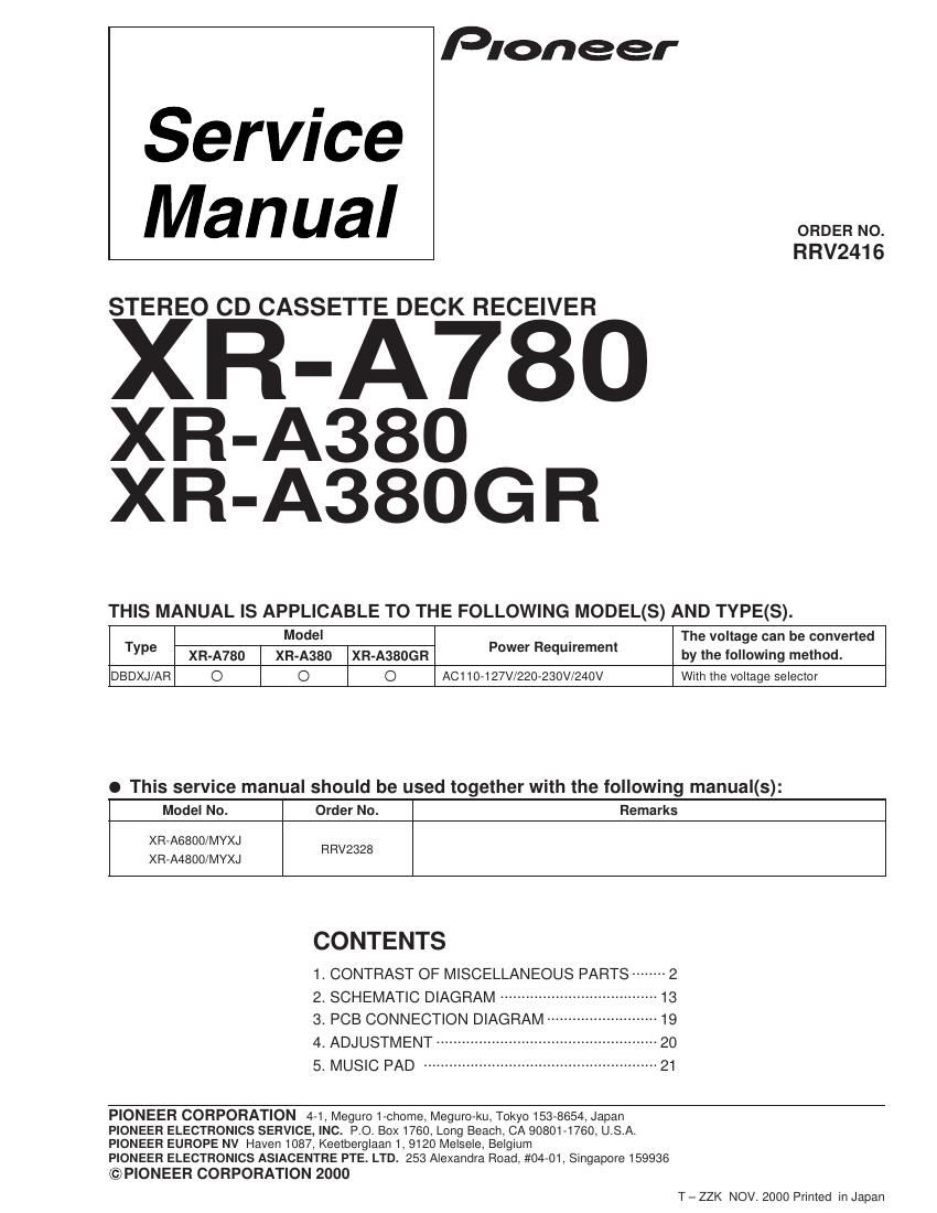
This is the 26 pages manual for pioneer xra 780 service manual.
Read or download the pdf for free. If you want to contribute, please upload pdfs to audioservicemanuals.wetransfer.com.
Extracted text from pioneer xra 780 service manual (Ocr-read)
Page 1
Service
Manual
Pioneer
STEREO CD CASSETTE DECK RECEIVER
XR-A780
XR-A38O
XR-A380G R
THIS MANUAL IS APPLICABLE TO THE FOLLOWING MODEL(S) AND TYPE(S).
ORDER NO.
RRV2416
T Model P R _ t The voltage can be converted
we XR-A780 xn-Asso xn-AssoGR °e' equ'reme by the following method.
DBDXJ/AR O O O AC110-127V/220-23OV/240V With the voltage selector
o This service manual should be used together with the following manual(s):
Model No. Order No. Remarks
XFl-A6800/MYXJ RRV2328
XFl-A4800/MYXJ
CONTENTS
1. CONTRAST OF MISCELLANEOUS PARTS -------- 2
2. SCHEMATIC DIAGRAM ---------------
3. PCB CONNECTION DIAGRAM-
4. ADJUSTMENT ..............................
........ 13
'19
...20
5- MUSIC PAD ....................................................... 21
PIONEER CORPORATION 4-1, Meguro 1-chome, Meguro-ku, Tokyo 153-8654, Japan
PIONEER ELECTRONICS SERVICE, INC. P.O. BOX1760, Long Beach, CA 90801-1760, U.S.A.
PIONEER EUROPE NV Haven 1087, Keetberglaan 1, 9120 Melsele, Belgium
PIONEER ELECTRONICS ASIACENTRE PTE. LTD. 253 Alexandra Road, #04-01, Singapore 159936
©P|ONEER CORPORATION 2000
T - ZZK NOV. 2000 Printed in Japan
Page 2
XR-A780, XR-A380, XR-A380GR
1. CONTRAST OF MISCELLANEOUS PARTS
NOTES: 0 Parts marked by "NSF" are generally unavailable because they are not in our Master Spare Parts List.
0 The /I\\ markfound on some component parts indicates the importance of the safety factor of the part.
Therefore, when replacing, be sure to use parts of identical designation.
0 Screws adjacent to Y mark on product are used for disassembly.
lReference Nos. indicate the pages and Nos. in the service manual for the base model.
I When ordering resistors, first convert resistance values into codeform as shown in thefollowing examples.
Ex] When there are 2 effective digits (any digit apartfrom 0), such as 560 ohm and 47k ohm (tolerance is shown by J=5%,
and K=10%).
560 - 56 X 10 - 561
47k a 47X 10 a 473
0.5 - R50
l - 1R0 -- -
Ex.2 When there are 3 eflective di ts (such as in high prec ion metalfilm re.
5.6Zk * 562 X 10 _ 5621
l CONTRAST TABLE for XR-A780
tors ).
----- RNI/4PC-
----- REP-EEK
IF
XR»A780/DBDXJ/AFI and XR-A6800/MYXJ are constructed the same except for the following :
Part No.
Ref. No. Mark Symbol and Description XR-A6800 XR-A780 Remarks
/MYXJ /DBDXJ/AR
PCB ASSEMBLIES
MAIN ASSY XWM3163 XWM3161
P5- 1 L AF ASSY XWZ3310 XWZ3303
COMPLEX ASSY XWM3168 XWM3165
P5- 3 PRIMARY ASSY XWZ3312 XWZ3291
P7- 1 DISPLAY ASSY XWZ3311 XWZ3305
P5- 4 FM/AM TUNER Module AXQ7068 AXQ7065
PACKING SECTION
P3- 1 A Power Cord ADG1154 XDG3009
P3- 2 FM Antenna ADH7005 ADH7004
P3- 6 NSP Dry Cell Battery (FISP, AA) VEM-O13 Not used
P3-10 Packing Case XHD3143 XHD3130
P3-11 NSP Warranty Card ARY7022 Not used
P3-13 Operating Instructions (English/French) XRE3030 Not used
P3-14 Operating Instructions (Italian/Dutch/German) XRC3020 Not used
P3-15 Operating Instructions (Portuguese/Swedish/Spanish) XR63021 Not used
Operating Instructions (English/Chinese/Spanish) Not used XRE3032
EXTERIOR SECTION
P5- 6 A Ceramic Capacitor (C1) CKPUYB102K50 Not used
P5-15 Rear Panel XNC3058 XNC3061
P5-17 Earth Plate XNGGO15 Not used
P5-3O Caution Label HE PFIW1233 Not used
P5-31 Caution Label VFIW1094 Not used
P5-36 NSP Getter XAX3169 XAX3172
A Fuse (FU2, FU3 :T3.15A) Not used AEK1059 *1
Fuse Card (For FU2, FU3) Not used AAX7493 *2
NSP Name Label Not used XAL3063 *3
FRONT PANEL SECTION
P7-26 Display Panel XAK313O XAK3132
P7-36 Power Button XAD3044 XAD3043
P7-38 SC Button XAD3046 XAD3060
P7-42 Sub Panel XAK3199 XAK3200
Notes : For PCB ASSEMBLIES, Refer to CONTRAST OF PCB ASSEMBLIES", 2. SCHEMATIC DIAGRAM and 3. PCB CONNECA
TION DIAGRAM".
*1 Refer to 2. SCHEMATIC DIAGRAM.
*2 Stick Fuse Card on the PRIMARY ASSY.
*3 Stick Name Label on the Rear Panel.