Pioneer xra 370 sw service manual
This is the 9 pages manual for pioneer xra 370 sw service manual.
Read or download the pdf for free. If you want to contribute, please upload pdfs to audioservicemanuals.wetransfer.com.
Extracted text from pioneer xra 370 sw service manual (Ocr-read)
Page 1
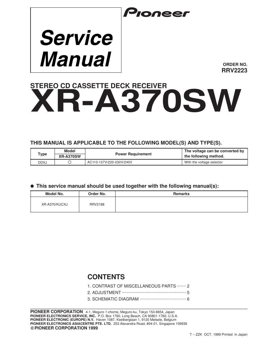
Service
Manual
STEREO CD CASSETTE DECK RECEIVER
Pioneer
ORDER NO.
RRV2223
XR-A37OSW
THIS MANUAL IS APPLICABLE TO THE FOLLOWING MODEL(S) AND TYPE(S).
T Model P R _ t The voltage can be converted by
6 XR-A37OSW °e' equ'reme" the following method.
DDXJ O AC110-127V/220-230V/240V With the voltage selector
I This service manual should be used together with the following manual(s):
Model No. Order No. Remarks
XR-A370/KUCXJ RRV2188
CONTENTS
1. CONTRAST OF MISCELLANEOUS PARTS -------- 2
2. ADJUSTMENT ...................
3. SCHEMATIC DIAGRAM
PIONEER CORPORATION 4-1, Meguro 1-chome, Meguro-ku, Tokyo 153-8654, Japan
PIONEER ELECTRONICS SERVICE, INC. P.O. BOX1760, Long Beach, CA 90801-1760, U.S.A.
PIONEER ELECTRONIC (EUROPE) N.V. Haven 1087, Keetberglaan 1, 9120 Melsele, Belgium
PIONEER ELECTRONICS ASIACENTRE PTE. LTD. 253 Alexandra Road, #04-01, Singapore 159936
© PIONEER CORPORATION 1999
T -ZZK OCT. 1999 Printed in Japan
Page 2
XR-A37OSW
1. CONTRAST OF MISCELLANEOUS PARTS
NOTES: OParts marked by "NSF" are generally unavailable because they are not in our Master Spare Parts List.
I The /I\ markfound on some component parts indicates the importance of the safety factor of the part.
Therefore, when replacing, be sure to use parts of identical designation.
0 Screws adjacent to Y mark on product are used for disassembly.
lReference Nos. indicate the pages and Nos. in the service manual for the base model.
I When ordering resistors, first convert resistance values into codeform as shown in thefollowing examples.
Ex! When there are 2 effective digits (any digit apartfrom 0), such as 560 ohm and 47k ohm (tolerance is shown by J=5%,
and K=10%).
560 - 56 X 10 - 561 ------------------------------
47k a 47 X 10 a 473
0.5 - R50 --
1 - 1R0 - RSIP-EflK
EX.2 When there are 3 eflective digits (such as in high precision metalfilm resistors).
5.6Zk d 562 X 10 ~ 5621 --------- -- ----- RNI/4PCI
l CONTRAST TABLE
XR»A37OSW/DDXJ and XR-A370/KUCXJ are constructed the same except for the following :
Part No.
Ref. No. Mark Symbol and Description XR-A370 XR-A37OSW Remarks
/KUCXJ /DDXJ
PCB ASSEMBLIES
COMPLEX ASSY XWM3108 XWM3105
P6- 2 PRIMARY ASSY XWZ3224 XWZ3222
PG- 3 SUB TRANS ASSY XWZ3227 XW23226
P9- 1 DISPLAY ASSY XWZ3209 XWZ3204
P6- 5 FM/AM TUNER Module AXQ7065 AXQ7062
PACKING SECTION
P4- 1 A Power Cord ADG7022 ADG1158
P4- 6 NSF Dry Cell Battery (RGP, AA) VEM-013 Not used
P4-1O Packing Case XH D3082 XHD3085
P4-11 NSP Warranty Card ARY7033 Not used
P4-13 Operating Instructions (English/French) XRE3024 Not used
Operating Instructions Not used XRE3028
(English/Arabian/Flussian)
SW Antenna Not used ADH7006 Accessories
EXTERIOR SECTION
PG- 7 A Power Transformer (AC120V) XTS3017 Not used
P6- 7 A Power Transformer Not used XTS3015
(AC110-127V/220-230V/240V)
P6- 8 A Fuse (FU1 25A) REK1083 Not used
P6- 8 A Fuse (FU1 :T4A) Not used AEK1060
P6- 9 NSP Fuse Caution Label XAX3122 Not used
P6-20 Rear Panel XNC3035 XNC3037
P6-35 NSP Fuse Label AAX7097 Not used
P6-43 NSP Getter XAX3138 XAX3140
P6-45 65 Label ORW1069 Not used
A Fuse (FU2, FU3 :T2A) Not used AEK1057 *1
NSF Name Label Not used XAL3029 *2
FRONT PANEL SECTION
P9-17 Display Panel XAK3108 XAK3109
P9-19 FL Cover XAK3088 XAK3124
P9-24 POWER Button XAD3027 XAD3033
P9-30 Sub Panel XAK3080 XAK3081
Notes :For PCB ASSEMBLIES. Refer to CONTRAST OF PCB ASSEMBLIES and 3. SCHEMATIC DIAGRAM.
*1 Refer to 3. SCHEMATIC DIAGRAM".
*2 Stick Name Label on Rear Panel.