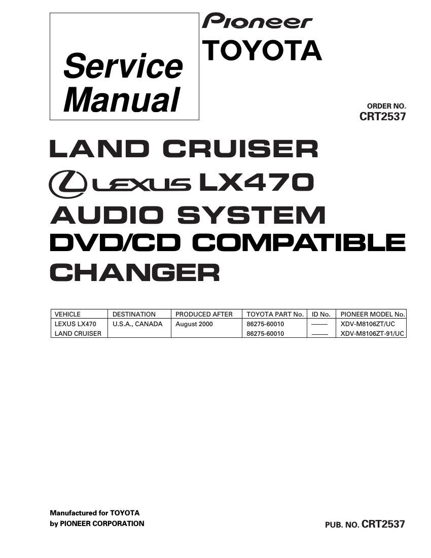
Pioneer xdvm 8106 zt service manual
This is the 116 pages manual for pioneer xdvm 8106 zt service manual.
Read or download the pdf for free. If you want to contribute, please upload pdfs to audioservicemanuals.wetransfer.com.
Extracted text from pioneer xdvm 8106 zt service manual (Ocr-read)
Page 1
2 XDV-M8106ZT,M8106ZT-91 -DVD Player Service Precautions 1. Never adjust the LD VR in the pickup unit to protect the pickup from electrical damages. 2. For pickup unit(CGY2020) handling, please refer to"Disassembly"(see page 88). During replacement, handling precautions shall be taken to prevent an electrostatic discharge(set the short switch of the pickup unit to the SHORT side).3. During disassembly, be sure to turn the power off since an internal IC might be destroyed when a connector is plugged or unplugged. 4. Please adjusting the skew after changing the pickup unit(see page 63). -This service manual should be used together with the following manual(s): Model No. Order No. Mech. Module Remarks CX-692 CRT2533 MM-1 DVD/CD Mech. Unit:Circuit Description, Mech.Description, Disassembly -Manufactured under license from Dolby Laboratories. "Dolby" and the double-D symbol are trademarks of Dolby Laboratories. Confidential unpublished works. © 1992-1997 Dolby Laboratories. All rights reserved. -Manufactured under license from Digital Theater Systems, Inc. -XDV-M8106ZT/UC and XDV-M8106ZT-91/UC have adopted AVC-LAN. -The supplementary models are identical with the original ones except for the following items. Description Part No. Cover CEG1026 Carton CHG3080 Contain Box(1/2) CHD3080 Protector CHP2333 Protector CHP2334 Air Cap CEG1288(Non Spare Part)
Page 2
3 XDV-M8106ZT,M8106ZT-91 1. SAFETY INFORMATION This service manual is intended for qualified service technicians; it is not meant for the casual do-it-yourselfer. Qualified technicians have the necessary test equipment and tools, and have been trained to properly and safely repair complex products such as those covered by this manual. Improperly performed repairs can adversely affect the safety and reliability of the product and may void the warranty. If you are not qualified to perform the repair of this product properly and safely; you should not risk trying to do so and refer the repair to a qualified service technician. CONTENTS 1. SAFETY INFORMATION ............................................3 2. EXPLODED VIEWS AND PARTS LIST.......................4 3. BLOCK DIAGRAM AND SCHEMATIC DIAGRAM ...10 4. PCB CONNECTION DIAGRAM ................................34 5. ELECTRICAL PARTS LIST ........................................48 6. ADJUSTMENT..........................................................587. GENERAL INFORMATION .......................................69 7.1 DIAGNOSIS ........................................................69 7.1.1 TEST MODE ..............................................69 7.1.2 DISASSEMBLY .........................................87 7.1.3 CONNECTOR FUNCTION DESCRIPTION89 7.2 IC ........................................................................90 7.3 EXPLANATION .................................................113 7.3.1 OPERATIONAL FLOW CHART ...............113 7.3.2 SYSTEM BLOCK DIAGRAM...................114 8. OPERATIONS AND SPECIFICATIONS ..................115