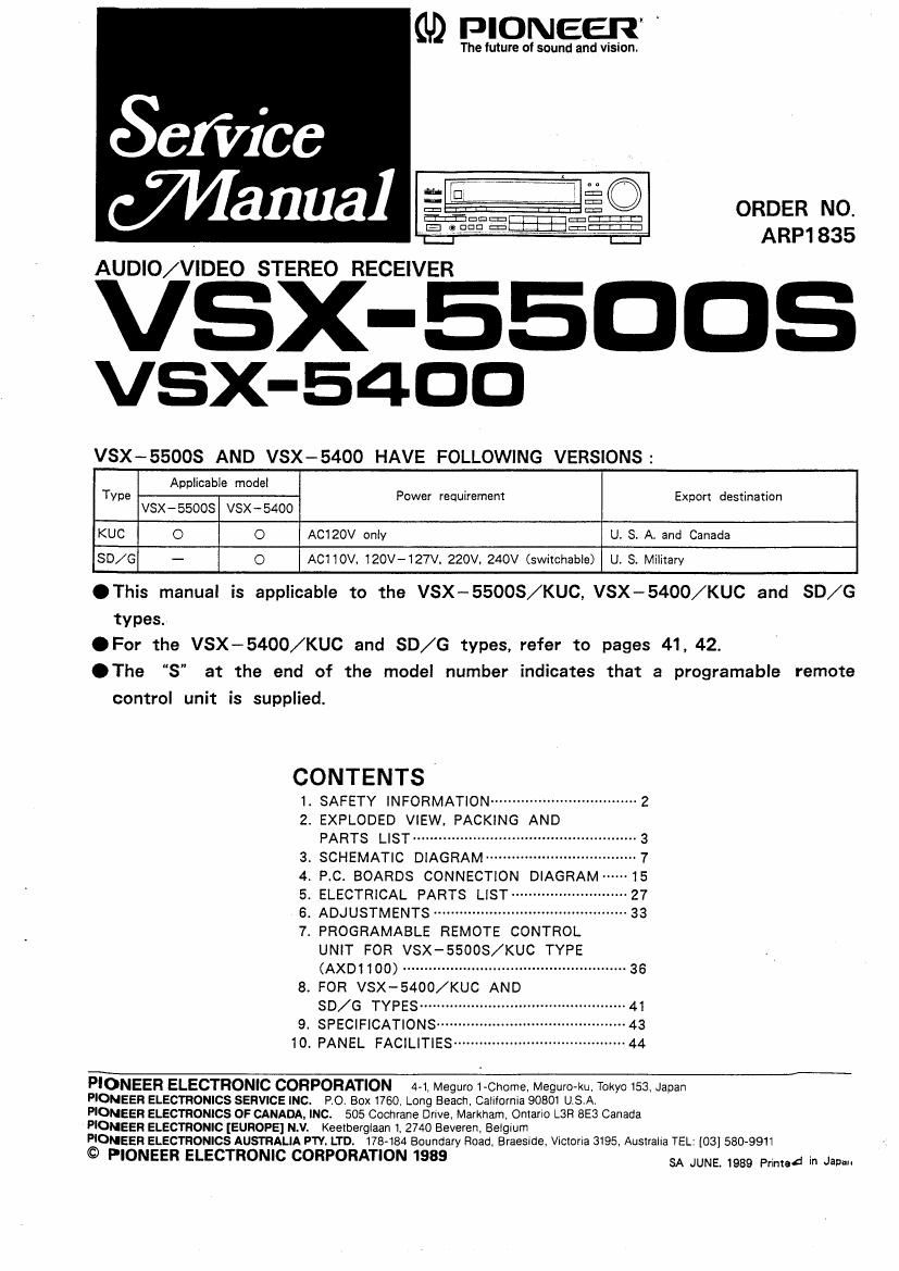
Pioneer vsx 5400 service manual
This is the 37 pages manual for pioneer vsx 5400 service manual.
Read or download the pdf for free. If you want to contribute, please upload pdfs to audioservicemanuals.wetransfer.com.
Extracted text from pioneer vsx 5400 service manual (Ocr-read)
Page 1
(ID PIONEER
The future of sound and vision.
i e 50 ORDER No.
"a QFElgwwggig ARP1835
AUDIO/VIDEO STEREO RECEIVER
VSX-EED
vsx-54oo
VSX-SSOOS AND VSX-5400 HAVE FOLLOWING VERSIONS:
Applicable model
TYpe Power requirement Export destination
VSX-SSOOS VSX-54OO
KUC O O ACIZOV only U. 3. AI and Canada
SD/G - O ACIIOV. 120V-127V, 220V. 240V (swiichabie) U. S. Miiiiary
.This manual is applicable to the VSX-SEOOS/KUC, VSX-5400/KUC and 80/6
types.
.For the VSX-5400/KUC and 80/6 types, refer to pages 41, 42.
.The S" at the end of the model number indicates that a programable remote
control unit is supplied.
CONTENTS
1. SAFETY INFORMATION .................................. 2
2. EXPLODED VIEw. PACKING AND
PARTS LIST ...................
SCHEMATIC DIAGRAM"
P.C. BOARDS CONNECTION DIAGRAM~
ELECTRICAL PARTS LIST---
. ADJUSTMENTS .....................
. PROGRAMABLE REMOTE CONTROL
UNIT FOR vsx-ssoos/KUC TYPE
(AXDIIOO) .................................................... 35
8. FOR vsx-5400/KUC AND
SD/G TYPES --------
9. SPECIFICATIONS
10. PANEL FACILITIES-u
«were
...41
~43
... 44
PIONEER ELECTRONIC CORPORATION 4-1, Meguro 1-Chome, MegurO-ku. Tokyo 153, Japan
PIONEER ELECTRONICS SERVICE INC. PO. Box 1760. Long Beach California 90801 USA.
PIONEER ELECTRONICS OF CANADA, INC. 505 Cochiane Drive, Markham, Ontario L3H 8E3 Canada
PIONEER ELECTRONIC [EUROPE] N.V. Keetberglaan 1. 2740 Beveren, BeIqum
PIONEER ELECTRONICS AUSTRALIA PTY. LTD. 178-184 Boundary Road, Braeside, ViciOna 3195, Australia TEL: [03] 580-9911
© PIONEER ELECTRONIC CORPORATION 1989 SA JUNE 1989 PM, In Jam
Page 2
VSX 5008
1. SAFETY INFORMATION
1. SAFETY PRECAUTIONS
The following check should be performed for the
continued protection of the customer and service tech-
nician.
LEAKAGE CURRENT CHECK
Measure leakage current to a known earth ground
(water pipe, conduit, etc.) by connecting a leakage current
tester such as Simpson Model 2292 or equivalent between
the earth ground and all exposed metal parts of the appli-
ance (input/output terminals, screwheads, metal overlays,
control shaft, etc.). Plug the AC line cord of the appliance
directly into a 120V AC 60Hz outlet and turn the AC
power switch on. Any current measured must not exceed
0.5mA
o
Leakage
Reading should
not be above
Device current OrEmA
under tester
test
Test all
exposed metal
surfaces
2-wrre cord
© Also test wtth .
plug reversed g, Earth
(Using AC adapter ground
plug as required)
AC Leakage Test
ANY MEASUREMENTS NOT WITHIN THE LIMITS
OUTLINED ABOVE ARE INDICATIVE OF A P0-
TENTIAL SHOCK HAZARD AND MUST BE COR-
RECTED BEFORE RETURNING THE APPLIANCE
TO THE CUSTOMER.
2. PRODUCT SAFETY NOTICE
Many electrical and mechanical parts in the appliance
have special safety related characteristics These are often
not evident from visual inspection nor the protection
afforded by them necessarily can be obtained by using
replacement components rated for voltage, wattage, etc.
Replacement parts which have these special safety charac~
teristics are identified in this Service Manual.
Electrical components having such features are identified
by marking with 3A on the schematics and on the parts
list in this Service Manual.
The use of a substitute replacement component which
dose not have the same safety characteristics as the
PIONEER recommended replacement one, shown in the
parts list in this Service Manual, may create shock, fire.
or other hazards.
Product Safety is continuously under review and new
instructions are issued from time to time. For the latest
information, always consult the current PIONEER Service
Manual, A subscription to, or additional copies of, PIONEER
Service Manual may be obtained at a nominal charge from
PIONEER,
- NOTE FOR INSTALLATION OF VR LED ASSEMBLY
Step 1 : Run the lead wrre (No.13) through the hole
indicated by the arrow in the Fig, below from
the face of panel base (N034).
Front panel face
VF? knob hole
Step 2: Run the lead wtre through the spaces between
the bosses at the rear side of the panel base
as shown in the Fig below.
Run one of the wrres through the spaces
between boss 1 and boss 2. and boss 4 and
boss 5. and the other through the spaces
between boss 2 and boss 3. and boss 5 and
boss 6.
(Insert the wrres deep between the bosses.)
\
Hi? "i. \