Pioneer TXD 1000 Owners Manual 2

This is the 7 pages manual for Pioneer TXD 1000 Owners Manual 2.
Read or download the pdf for free. If you want to contribute, please upload pdfs to audioservicemanuals.wetransfer.com.

Page: 1 / 7
Pioneer TXD 1000 Owners Manual 2

Extracted text from Pioneer TXD 1000 Owners Manual 2 (Ocr-read)


Page 1

FM/AM DIGITAL SYNTHESIZED TUNER GDPIONEER'

X-D'IDDD s.

OPERATING INSTRUCTIONS

Before turning on the power, please confirm the
setting of the line VOLTAGE SELECTOR switch
on the rear panel. If it is not set properly, change
the setting of it according to the LINE VOLTAGE
SELECTOR SWITCH on page 3.

NOTE:

The operating instructions apply to two versions of the
TX~D1000. The TXrDIOOO/S/G model is supplied with
the rack mount adaptors as an accessory. while the
TX-DIUOO/S model is not supplied with it. Follow the
procedure outlined below for attaching the rack mount
adaptors to the TX-DIOOO.

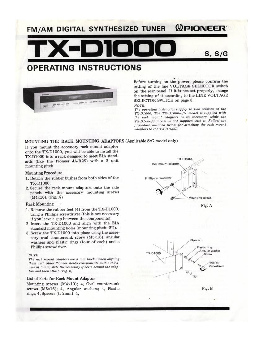
MOUNTING THE RACK MOUNTING ADAPTORS (Applicable S/G model only)
If you mount the accessory rack mount adaptor
onto the TX-DlOOO, you will be able to install the
TX-DlOOO into a rack designed to meet EIA stand-

ards (like the Pioneer JA-RZS) with a 2 unit TX'01°°°\
mounting pitch. Rack mount adaptor
Mounting Procedure
1. Detach the rubber bushes from both sides of the Phllllps screwdriver

TXleOOO. /
2, Secure the rack mount adaptors onto the side K

panels with the accessory mounting screws 3/

(M4X10). (Fig. A) Mounting screws
Rack Mounting

F . A
1. Remove the rubber feet (4) from the TX-DlOOO, 1g

using a Phillips screwdriver (this is not necessary
if you leave a gap between the components).
2. Insert the TX-D1000 and align with the EIA
standard mounting holes (mounting pitch: 2U).
3. Screw the TX-DlOOO into place using the acces-
sory oval countersunk screw (M5x16), angular
washers and plastic rings (four of each) and a (5935")

.
Phillips screwdriver. \-\ / Plastic ring

NOTE: TX»D1000

1 K/ Angular washer
>1: s Sm
The rack mount adapters are 3 mm thick. When aligning X/ Jr/
them with other Pioneer steréo components with a thick: PIIIIIIDS

ness of 5 mm, slide the accessory spacers behind the adap- \ tors and then attach (Fig. B).

List of Parts for Rack Mount Adaptor // - i 6 Q29

Mounting screws (M4X10); 4, Oval countersunk
screws (M5x16); 4, Angular washers; 4, Plastic Fig.B
rings; 4, Spacers (t: 2mm); 4,

Page 2

Features t . . l 2
Rear Panel Facilities ....... 3
Antenna and Ground Connections ........ 4
Stereo Amplifier Connection . , ......... 5
Front Panel Facilities .................. 6

CONTENTS

Listening to the Broadcasts ............. 8
Conditions Frequently Mistaken fur
Malfunctions 9
Technical Deacrlpt'lon .................. 10
Specifications ........................ 12

The big features with a digilal synihesiled tuner are
pronounced tuning ease and accurate tuning. Three
dlflflrlrll iunlng rrieLhods are possible Willi the TX-DIOOO.

. Aum Scan Tuning: By degrexwd the UP and DOWN
tuning switches, the tuning automatically stops when a
bruadcasr l's rzceived.

2 Manual Tuning: When thc tuning mode switch is sci
Lu MANUAL, manual lunlng is possible at every
SOkHz for FM reception and a! everv (Hz for AM
rcccptiorr.

. Preset Tunin Up to six stations each lot FM and
AM can be stored in the mcmory and then calizd by
fingprtip ooriirnl using rhc push billions.

With syndieslled timers, [here is a tendency in concentrate
only on improved operating case. hesidcs accurate tuning
oi course, and to ignore the performance and sound quality
which traditional timers are expected to display. At least,
(Ills Is the (as: when viewed from th: siandpoinl 9' In:
ourpur signal quality. However, wirh inc Tx-mooo, our
many years of dedication to techniouos ainicd ar reprrr
ducing rhe original sound Iaiililully merge with our quaru
synthesized techniques to oring you a superior audio
program sourcc in which we have the utmost conndcnce.

w

FEATURES

RF Section Featuring Control with LSI Synlhc-
siler

Th: from end and local oscillalnr employ a quarrZ Oscilla-
on as a sunrise ol iiic rcrcrcnoe signal, and this is tornroiicd
by the synthesiler F'LL circuit, This provides accuratt
tuning with tho broadcasting station ircoucncy, SOkHz
intervals ior FM and QkHz or IOkHz intervals lor AM,and
thc signal is locked so that the tuncr maintains its past pcir
iormance. in addition, the RF amplifier which umpluys a
dual-gate M05 FET and Lllc varacror diode, which is selcct-
ed under strict quality ccnxrul sundards, enhance the noise
iactor, and by ihzir sensitivity and ability to suppress inter
icicncc Ihey home in on thc dcslred signals in a complex
signal environment.

PLL Synthesiler which Adds a New Dimcnsion

to Operating Ease

Quartz PLL synthesizers have made ii possible to rcceive
signals stahly and with a high dtgree of precision. This
tuner. howtvcr. goes a step furthar. it oficrs FM auto scan
tuning whcrc the slations arc timed automatically, and
manual tuning which enables slations to be pictcd up at
fingerIrip wnlml at soirrla intervals lor FM reception and
ar 9kHl or IDkHz intervals for AM. Furthermore, [here is a
memory function capable of storing up [D 5 smlians null
for AM and FM. Once die frequencies or me stations have
neon srorcd in the memory, thcy can be called back at uic
touch or a lsutron. The reception mode is indicated by a
digital display, and rhcrc is also a memory display and a
signal indicaror which mates tuning much czsicr.
High-performance IF Scction

in order to do iustlos to the leaiures o1 ill: high
performance quaril synth sizer system and also to chiain
the has! In audio ape cations, a linear atlas: ceramic
filler is cmpioycd which allows the group delay character
isiics, which have a hearing on the distortion and
resolution, to be flat

ILL MPX with Self-cunuined Auto Pilot Signal
Cancelcr

This toner incorporarcs Pioneer original aum pilot signal
cancclcr which tracks thc pilot signal lcvel, and an
NFB PLL MPX dacodcr. Togothcr, they help yield irnprovc-
mcnts in the overall charactcrisrics such asa signal~Ko-noisc
ratio of 72dB, distortion oi 0,06% and a separation of
Sir! as well as a widcsrange frcoucncv rcsponsc of 2qu to
i5kHztޤdB

Off-air Recording Function

A buili»in oscillator generalcs 330Hz referencz signals
(50% modulation) which are exircmuly handy fur recording
programs omhc alr (FM)

REAR PANEL FACILITIES

PIONEER

,-.

is tall

H4 'i

i @i/ ®

@ FM ANTENNA INPUT TERMINAL FOR
75-0HM CDAXIAL CABLE
Canned a 75-ohrn coaxial cnolc to this terminal when
using it at the loader [mm the FM antenna,

(D FM ANTENNA INPUT TERMINALS FOR
(IDOHM TWIN-LEAD FEEDER
(nnnacl a souphm twin-lead isedcr to those terminals
when using it as the reader iron. the FM antenna Use
these terminals when connecting the accessory T-Lype
FM Wei-ml

6) GND TERMINAL
This I! that ground terminal From aspecu of both safely
and reduced noise, connect 2 ground land to thir terminal.

(45 AM ANTENNA INPUT TERMINAL

When using In External AM antenna. connect it to this
terminal.

{5:1 AM BAR ANTENNA
This antenna is for AM hrordcasti Set it where the
optimum reception is ohtaii-itd,

@/ OUTPUT JACKS
Connect these lemlinnli with (10 tuner input lgrmlmalts on
your ergo amplifier

(3 FM DE-EMPHASIS SWITCH

This switch is used to aided. the daramphuia value Benn:
the tuner leavas Lhc minulntcurinz plant, ii. is set to the
dltmpIiaI-ia lai the [mini dutinaiion. For the US and
Canada, it is ml to 75in, and [or other countries to
sous, check thal the switch it rel properly belure use,
If the switch is act to the wvoni Waitinn. in. Ingli-
(gummy range sound will appear dlimrkd dining the
reception or an FM orordcast. Contact your dealer and
inquire if you Ire lioI liiu about [he de-emphul: in yullr
area, (2514:: when receiving an FM Dolby broadcutlng)

0 AM FREQUENCY LOCK SELECTOR

This switch is used to select the AM IF luck iroquanoy.
Sal lo leHz whzn retelvmg AM broadcasts in iii! us,
since the pro-dour strtion rrsouencras are set it IOItHz
{rcoucni-ic-i. act it iokHa ireouencies, Sci. to 9kHz when
receiving AM broadcasts in the area the mquoncy
intervals between the AM broadcasts are set at 9km.

C9) LINE VOLTAGE SELECTOR SWITCH
Check that the indication oi the switch is some :1 your
residence heiorc plugging the power cord into the outlet,
If it isn't or if you move to In iron where thr voluge
quire-(lento differ change the switrh icttrng as follows,
Before ndjiuiing, dis'connctt the power cord
Unscrew the hue cap with a Phillips sorcwdrlvor, than
take out the lust and mu!-

. Reinstall the plug with its cutaway lcction exposing
correct voltage indication as shown in Fig. A.

. item no the table and install a replacement ruse
(provided as an accessory l
insert the hire in the luso cap, then in the cap to tho
nlug ay-Il iilhlen,

N

m

o

v Soakar

d
%

v0 LTAGE SELECYDR
ulna
F ust

Pnllllpsscvawdvivar \
Fig. A
raoie
voiuyt rut.
IIGV, izav IA
22uv,26uv n.5A

@ POWER CORD

plug this into a power outi-t or an AC OUTLET on the
stereo amplifier