Pioneer tx 9800 brochure

This is the 4 pages manual for pioneer tx 9800 brochure.
Read or download the pdf for free. If you want to contribute, please upload pdfs to audioservicemanuals.wetransfer.com.

Page: 1 / 4
pioneer tx 9800 brochure

Extracted text from pioneer tx 9800 brochure (Ocr-read)


Page 1

Manufacturers Specifications

Selectrvtty: 30 dB, wide; 85 dB, narrow.

Image Rejectio : 70 dB.

PM Section

Mono Usable Sensitivity: 8.8 dBf
(1.5 uvi.

SCI-dB Quieting Sensitivity: Mono, 13.2
dBf (2.5 uV); stereo, 36.1 dBf (35 uV).
S/N at 85 dBf: Mono, 83 dB; stereo, 80
dB.

THD: Mono, 0.04 percent at 1 kHz,
0.05 percent at 100 Hz, 0.06 percent at
6 kHz, wide; stereo, 0.07 percent at 1
kHz, 0.1 percent at 100 Hz, 0.2 percent
at 10 kHz, wide.

Capture Ratio: 0.8 dB, wide; 2.0 dB,
narrow.

Frequency Response: 20 Hz to 15 kHz,
+0.2, -0.5 dB.

LP. and Spurious Rejection: 110 dB.
Image Rejection: 120 dB.

AM Suppression: 65 dB.

Subcarrier Rejection: 70 dB.

Muting Threshold: 19.2 dBf (5,0 uV),
Stereo Separation: 55 dB at 1 kHz, 40
dB from 20 Hz to 10 kHz.

AM Section

IHF Sensitivity, External Antenna:
15 uV.

Selectivity: 20 dB, wide; 50 dB, narrow.
S/N: 55 dB,

LF. Rejection: 65 dB,

Audio Section

Output Level, FM: 650 mV fixed, 50
mV to 1.3 V variable.

Output Level, AM, 30 Percent Modu-
lation: 200 mV fixed, 15 mV to 400 mV
variable.

General Specifications

Power Requirements: 120V, 60Hz,28w.
Dimensions: 17% in, (453 mm} W. x We
in. (155 mm) H. x 15% in. (390 mm) D.
Weight: 20.5 lbs. (9.3 kg).

Price: $450.00.

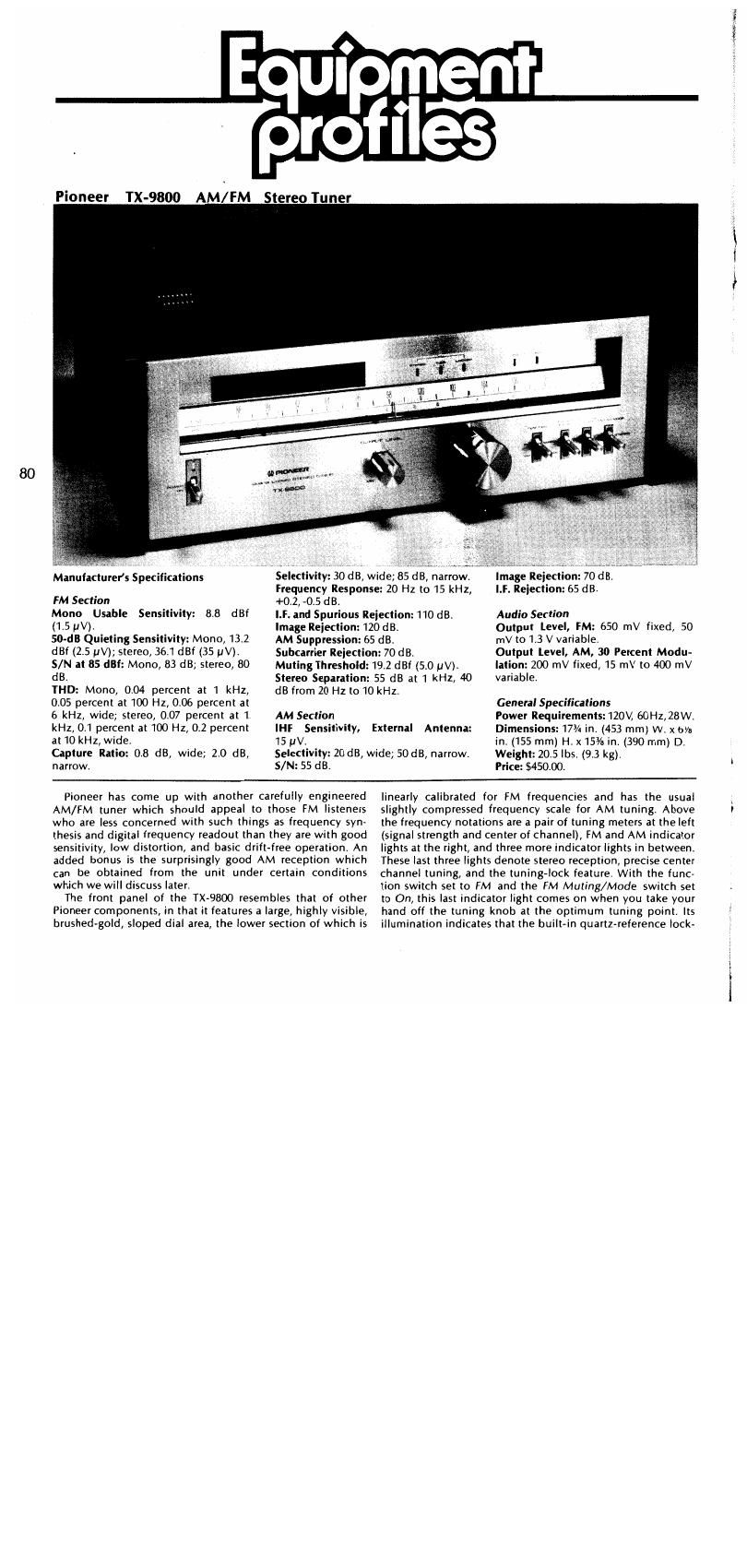
Pioneer has come up with another carefully engineered
AM/FM tuner which should appeal to those FM listeners
who are less concerned with such things as frequency syn-
thesis and digital frequency readout than they are with good
sensitivity, low distortion, and basic drift-free operation. An
added bonus is the surprisingly good AM reception which
can be obtained from the unit under certain conditions
which we will discuss later.

The front panel of the TX-9800 resembles that of other
Pioneer components, in that it features a large, highly visible,
brushed~gold, sloped dial area, the lower section of which is

linearly calibrated for FM frequencies and has the usual
slightly compressed frequency scale for AM tuning. Above
the frequency notations are a pair of tuning meters at the left
(signal strength and center of channel), FM and AM indicator
lights at the right, and three more indicator lights in between.
These last three lights denote stereo reception, precise center
channel tuning, and the tuning-lock feature. With the func-
tion switch set to FM and the FM Muting/Mode switch set
to On, this last indicator tight comes on when you take your
hand off the tuning knob at the optimum tuning point. Its
illumination indicates that the builtin quartz-reference lock-

ewMW-"vltm

Page 2

MICROWLYS. ACROSS 300- OHM ANTENNA TERMINALS
0.55 if"

.
l

' no.0
. 5m g 7055
STEREO mo - ope-r. '
mono mo - 0,03 9s

«a

.m

S
murmur: msmrmou - as

RELATIVE AMPLITUDE - dB

a mono 504- no: om

SIGNALiNPUT rowel-or tom - l x no"l WATTS]

Fig. 1 - Mono and stereo quieting and distortion
characteristics for the Wide Li. setting of the FM sec tion.

ing circuit has been activated by the touch»sensor detector
circuit associated with the tuning knob and that the frequen
cy of the local oscillator is locked to track the frequency of
the signal to which you-have tuned. Four small sliders called
"memory markers" can be positioned below the frequency
scales as a reminder of the frequency of most-tuned-to-sta-
tions.

Along the lower section of the front panel are a power on/
off toggle switch: a rotary Output Level control; a large,
flywheel-coupled tuning knob; AMrFM function selector
switch; a Narrow/Wide. toggle switch, an MPX-blend or
noise-filter switch, and the FM Mutiny/Mode switch previ-
ously referred to. Pioneer has taken the route of permitting
the muting feature to be turned off only when mono FM is
selected. While we have objected to this approach in the
past (preferring the ability to tune to very weak stereo FM
stations if we so choose), it turned out during our measure-
ments that Pioneer has set the muting threshold at a suffi-
ciently low level, just below the stereo switching threshold,
so that the muting switch arrangement poses no problems
under any practical listening conditions, _

The rear panel of the TX-QOO contains the usual array of
antenna terminals, for 75 or Jim-ohm FM transmission lines,
external AM antenna lead connection, and ground." lust
below these terminals are an FM de-emphasis switch (with
settings for standard 75microsecond or 25~microsecond de-
emphasis), and a switch which alters the sensitivity of the

momma soc-ours ANTENNA TERMINALS

00.65 L74


l
l
no.0
.
l
maze mo - me
who THD - mess

__-
-_

~40

\\

'3
"mm: orsrurrrmu -$

RELATIVE AWLITUDE-GB

5/ N
MONO SIN I 75GB STEREO I

to
SIGNAL INPUY FUNER- l (0 I I I I .g-IB WATTS)

Fig. 2 - As above for the Nanny. setting,

touch-sensor feature on the tuning knob. Fixed and variable
pairs of output jacks are centrally located nett to a pair of
"multipath" output jacks which may be connected to the
vertical and horizontal inputs of any oscilloscope for obser<
vation of multipath effects during antennarorientation. A
tw0 rear panel when it is tucked up against the chassis, but can
be pivoted downward and rotated for best AM reception. A
single a.c. convenience outlet is located at the lower right of
the rear panel and is not controlled by the power on/off
switch. ,

AUDIO 0 November 1979

0.0I

, citcuit and} sensitive, low-distortion iC. AGC voltage is sup-

~10


, MONO
- - STEREO

RELATIVE LEVEL - (IE

cremation-1.
,, v
S

19°! : lat ant

too ll _
_ _ FREQUENCY - it:
3,...- Distortion vs. frequency brthe Wide u.

CircuitHigh Ii ta

Atwostag'e gramplifier is used in the FM front end of the

Tit-9&1), along with a five-section tuning capacitor. Three

dualogate MOS-FEB are used in the r.f. stages. An automatic
,_ ontrol circuit is employed to safeguard against possi-

bie local oscillator drift which might be caused by fluctua-

tioosfit- temperature or humidity. The output of a self-con-

rliifiBdQuartz-crystal oscillator is divided-down to 100 kHz

and used as a reference signal for locking the local oscilla-
tortothedesired tuned-to frequency difference of 10.7 MHz.

The FM, and AM i.f. sections can be operated in either a
~wide~bancl or narrow-band mode. A dual-element, linear-
ptmse; ceramic filter is used in the FM wide-band mode,
whileamselement, linear-phase ceramic filter is used in the
narrowéband FM mode. '

The same type of approach is used in the AM_i.f. section. A
3fP¢ier 7-element. l.C bandpass filter is used in the AM wide-

2 :band Mode, while a narrow-band ceramic filter added to the

firstfilteris ernployed in the narrow mode. The AM front end
"3-gang, variable-capacitor-tuned type of r,f. amplifier

plied,_toeach section of the AM circuitry.

FM Performance Measurements _

Several tuners and receivers which we have recently tested
have employed dual-bandwidth i.f. sections but exhibited
little, if any, difference in performance when switched from
onemode- to the other, except for moderate changes in selec-
tivityLSuch is not the case with the TX-QBOD. Each mode has

its defiriiteuses and performance differences are significant,

so that aii of our measurements had to be made for both i.f.
bandwidth settings. Figure 1 is a plot of mono and stereo
quieting and distortion characteristics for a 1-kHz modulat-
ing signal (mt) percent modulation) when the tuner is oper-
ated in the Wide mode. Under these conditions, usable sen-
sitivity measured 1.7 pV (9.8 dBf), while the 50-dB quieting
point was reached with a signal strength of 2,8pV (14.1 dBf)
in mandSSrrV (36.1 dot) in stereo. Signal-to-noise ratio
" madameasured 75 d8 in mono and 70 dB in stereo,


for the Narrow i.f. setting.

MONO

0.10

DISTORTION - 5L
RELATIVE LEVEL - dB

(Nil

10 too ll
FREQUENCY - Hz

IOI 20k

81

as...»