Pioneer tx 9500 service manual

This is the 10 pages manual for pioneer tx 9500 service manual.
Read or download the pdf for free. If you want to contribute, please upload pdfs to audioservicemanuals.wetransfer.com.

Page: 1 / 10
pioneer tx 9500 service manual

Extracted text from pioneer tx 9500 service manual (Ocr-read)


Page 1

8. ADJUSTMENTS

Before starting adjustment, make sure that the
dial pointer indicates the left hand end of the
frequency scale (the lowest frequency position)

when the tuning knob is turned fully counter-
clockwise.

8.1 ADJUSTMENT OF FM SECTION

Caution:

Do not touch the IF transformers (T1 ~ T5) in
the AM-FM IF assembly.

FM front end

Switch positions:

FUNCTION switch: FM MONO
MPX NOISE FILTER switch: OFF
FM MUTING switch: OFF

Connection of instruments:

FM signal generator (FM SG): Connect to the
FM ANTENNA terminals through a SOC-ohm
dummy antenna.

AC voltmeter (with the maximum indication
of about 1V)! Connect to the FIXED L
terminal.

\_.._._... ____._._._.

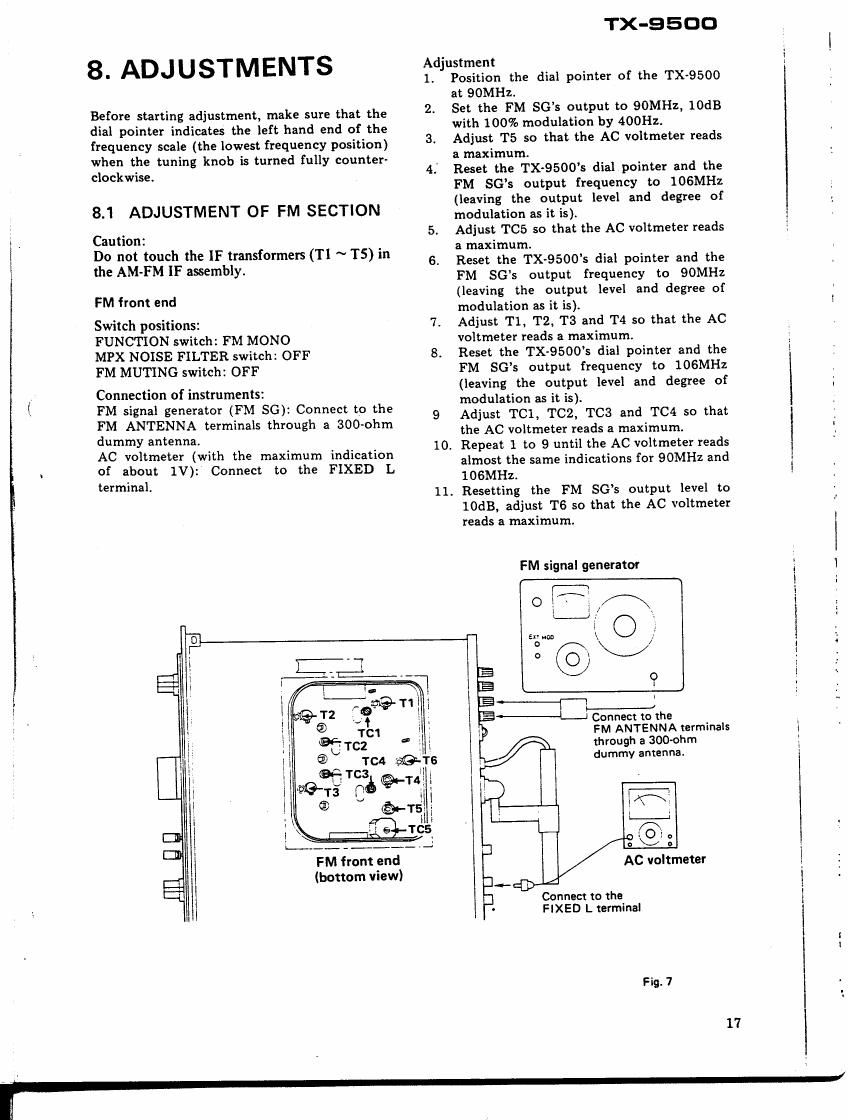
FM front end
(bonom View)

TX-QSOO

Adjustment

1. Position the dial pointer of the TX-9500
at QOMHz.

2. Set the FM SGs output to QOMHZ, 10dB
with 100% modulation by 4001-12.

3. Adjust T5 so that the AC voltmeter reads
a maximum.

4. Reset the TX~95005 dial pointer and the
FM SGs output frequency to 106MHz
(leaving the output level and degree of
modulation as it is).

5. Adjust TC5 so that the AC voltmeter reads
a maximum.

6. Reset the TX-9500's dial pointer and the
FM SGs output frequency to QOMHz
(leaving the output level and degree of
modulation as it is).

7. Adjust T1, T2, T3 and T4 so that the AC
voltmeter reads a maximum.

8. Reset the TX-9500s dial pointer and the
PM SGs output frequency to 106MHz
(leaving the output level and degree of
modulation as it is).

9 Adjust TCl, TC2. T03 and TC4 so that
the AC voltmeter reads a maximum.

10. Repeat 1 to 9 until the AC voltmeter reads
almost the same indications for SOMHZ and
106MHz.

11. Resetting the FM SGs output level to
IOdB, adjust T6 so that the AC voltmeter
reads a maximum.

FM signal generator


.
._.__z
[5:12 Connect to the

FM ANTENNA terminals
through a 300-ohm
dummy antenna.


WV,
. A .
3 . 8:
AC voltmeter
1-4}
Connect to the
3- FIXED L terminal

Fig. 7

17

Page 2

"array-u

II.

ll,l,l-]- ,_

fr} :-;:1 I '

m::

T NI,

en-

.'§ .:..

\J

Muting circuit

Switch positions:

FUNCTION switch: FM MONO
MPX NOISE FILTER switch: OFF
MUTING switch: OFF

Connection of instruments:

FM signal generator (FM SG). Connect to the
FM ANTENNA terminals through a 300-ohm
dummy antenna.

AC voltmeter (with the maximum indication
of about 1V): Connect to the FIXED L
terminal.

Distortion meter: Connect to terminal No.12
of the AM-FM IF assembly,

Adjustment

1. Turn VRl fully counterclockwise.

2. Setting the TX-SSOO to a condition, by
reducing the FM SGs output level (less
than -6dB) or detuning the TX-9500, such
that it is receiving no input signals, adjust
the primary (lower) core of T6 so that the
TUNING meter points to the center of the
scale.

Distortion meter

10.
11.

O

P cocoaoo oooc coco

oEE ::Jo
OO

/

a n
:39 can:
i. 1131:9151

Connect to terminal No.12
of the AM-FM 1F assembly.

18

Resetting the FM SGs output level to
60dB, adjust the secondary (upper) core
of T6 so that distortion becomes minimum.
Set the FM SGs output to QSMHZ, 20dB
with 100% modulation by 400Hz.

Tune the TX-9500 to 98MB: (Make a fine
tuning looking at the TUNING meter).

Set the MUTING switch at 1."

Turn VRI clockwise slowly and stop it
just when the AC voltmeter abruptly
indicates 0V.

Reset the MUTING switch "OFF".

Setting the TX-9500 to a condition, by
reducing the FM SGs output level (less
than -6dB), such that it is receiving no
input signals, adjust the primary (lower)
core of T6 so that the TUNING meter
points to the center of the scale.

Repeat 8 to 9 for several times.

Resetting the FM SGs output level to
IOOdB, adjust VR2 so that the SIGNAL
meter points to 5."

AC voltmeter

.69;

f
3 Connect to the

l FIXED L terminal.
I

i

l

/

-aj

FM signal generator

Connect to the FM
ANTENNA terminals
through a 300-ohm
dummy antenna.