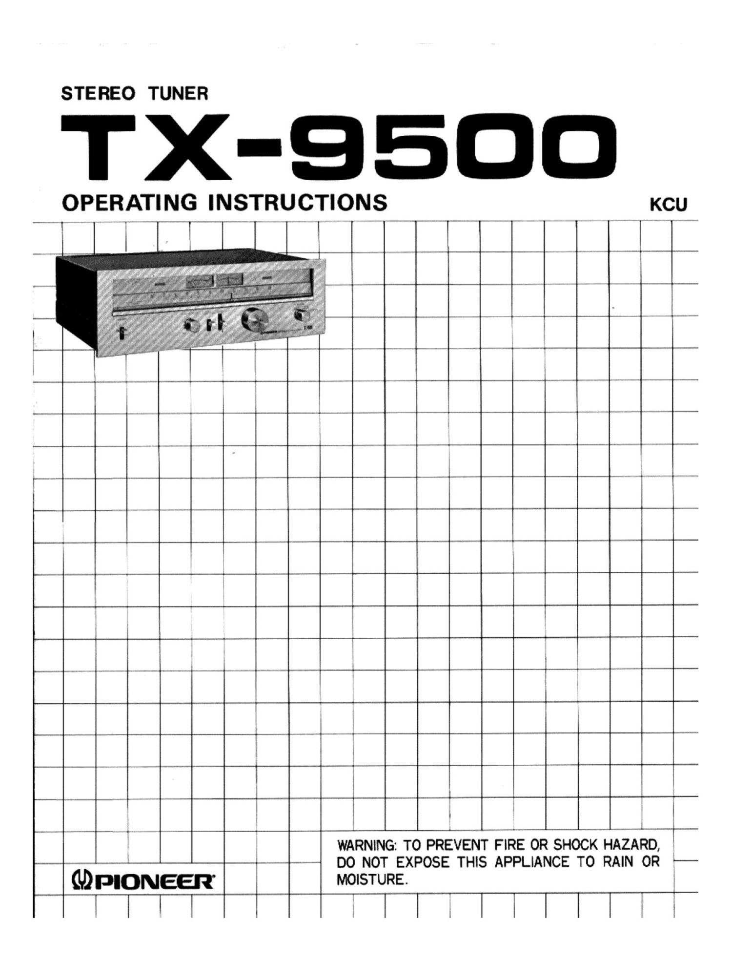
Pioneer tx 9500 owners manual
This is the 12 pages manual for pioneer tx 9500 owners manual.
Read or download the pdf for free. If you want to contribute, please upload pdfs to audioservicemanuals.wetransfer.com.
Extracted text from pioneer tx 9500 owners manual (Ocr-read)
Page 1
STEREO TUNER
TX-QEII
OPERATING INSTRUCTIONS KCU
I
J i
E
i
3
L
WARNING: TO PREVENT FIRE OR SHOCK HAZARD,
DO NOT EXPOSE THIS APPLIANCE T0 RAIN OR %-
GDPIONEER MOISTURE.
l||k Ellilllllx}
Page 2
CONTENTS
Broadcasts Reception ............... 7
Effective Operation ................. 8
Conditions Frequently Mistaken for
Malfunction ...................... 10
Specifications ..................... 11
Features ......................... 2
Installation Cautions ...... . ........ 2
Connection Diayam ............... 3
Connections .................. . . . . 4
i Antenna 8: Ground Connections ....... 4
Front Panel Facilities ............... 6
FEATU RES
S-gang Variable Capacitor Front End
The high frequency amplifier 2 stage from end employs a
S-gang variable capacitor and dual gate MOS FET. Imaging,
IF, spurious and other types of interference rejection are
greatly advanced. The local oscillator circuit is also provided
with a buffer amplifier for always stable FM reception even
in high field strength areas.
Newly Developed Ultra Wideband Linear Phase
Detector
A newly developed delay type ultra wideband linear phase
detector is employed. Coupled with the flatness of the
group time delay characteristic of the IF amplifier circuit,
it results in excellent linearity and high fidelity FM recep-
tion.
Wideband High Selectivity IF Amplifier
Seven integrated circuits and 4 stringently selected dual
element ceramic filters are utilized in the IF amplifier.
The circuitry expands bandwidth, controls phase charac-
teristics and compensates for group delay. High selectivity
and high AM suppression are also obtained from the strong
limiter operation. Ideal stereo reproduction can thus be
performed without interference from nearby stations.
Recording Level can be Checked
The built-in fundamental signal oscillator (level corresponds
to 50% FM modulation) allows the recording level to be
checked. It can be employed regularly for distortionless
recording of desired FM programs.
Magnificent FM Reception
An IC phase locked loop (PLL) system is employed in the
stereo demodulator. This is not affected by temperature
fluctuations or aging and results in superb frequency re-
sponse and high separation covering a wide bandwidth.
High and low frequency noise is cut by filters, so excellent
results can be obtained recording of FM programs.
High Performance IC AM Tuner
Greatly improved imaging and IF rejection are provided by
the tuned type high frequency amplifier circuit employing
a 3-gang variable capacitor. The AM section is completely
IC, with a precision ceramic filter for enhanced selectivity
and frequency response. Balanced type mixer circuit and
high performance AGC circuit assure stable reception with
low spurious interference and distortion, even in strong
field areas.
Human Engineered Panel Layout
Tuning is easy, aided by the long 250mm tuning scale,
large size meters, and positive-touch controls. The hand-
some front panel design of the new Pioneer stereo tuner
attests to its position of leadership in the stereo component
field.
INSTALLATION CAUTIONS
Avoid installing the TX.9500 in locations such as
the following.
o In direct sunlight, near radiators or other heat
sources.
0 Above a large heat producing power amplifier,
or near an amplifier power transformer.
0 Humid or dusty surroundings.
0 Unlevel or unstable supports, or where subject
to vibration.
Mumal interference can be caused if located too
close to an AM radio or TV set, allow for adequate
spacing.
2