Pioneer ta 909 service manual
This is the 20 pages manual for pioneer ta 909 service manual.
Read or download the pdf for free. If you want to contribute, please upload pdfs to audioservicemanuals.wetransfer.com.
Extracted text from pioneer ta 909 service manual (Ocr-read)
Page 1
SERVICEAULMNA ., .._, Wade
West Germany Model
E Model
' fifli
' Ell
___,_
- ===
_____
O BBBDBDB =3- 6: °
:::J a
O 5:,
a a
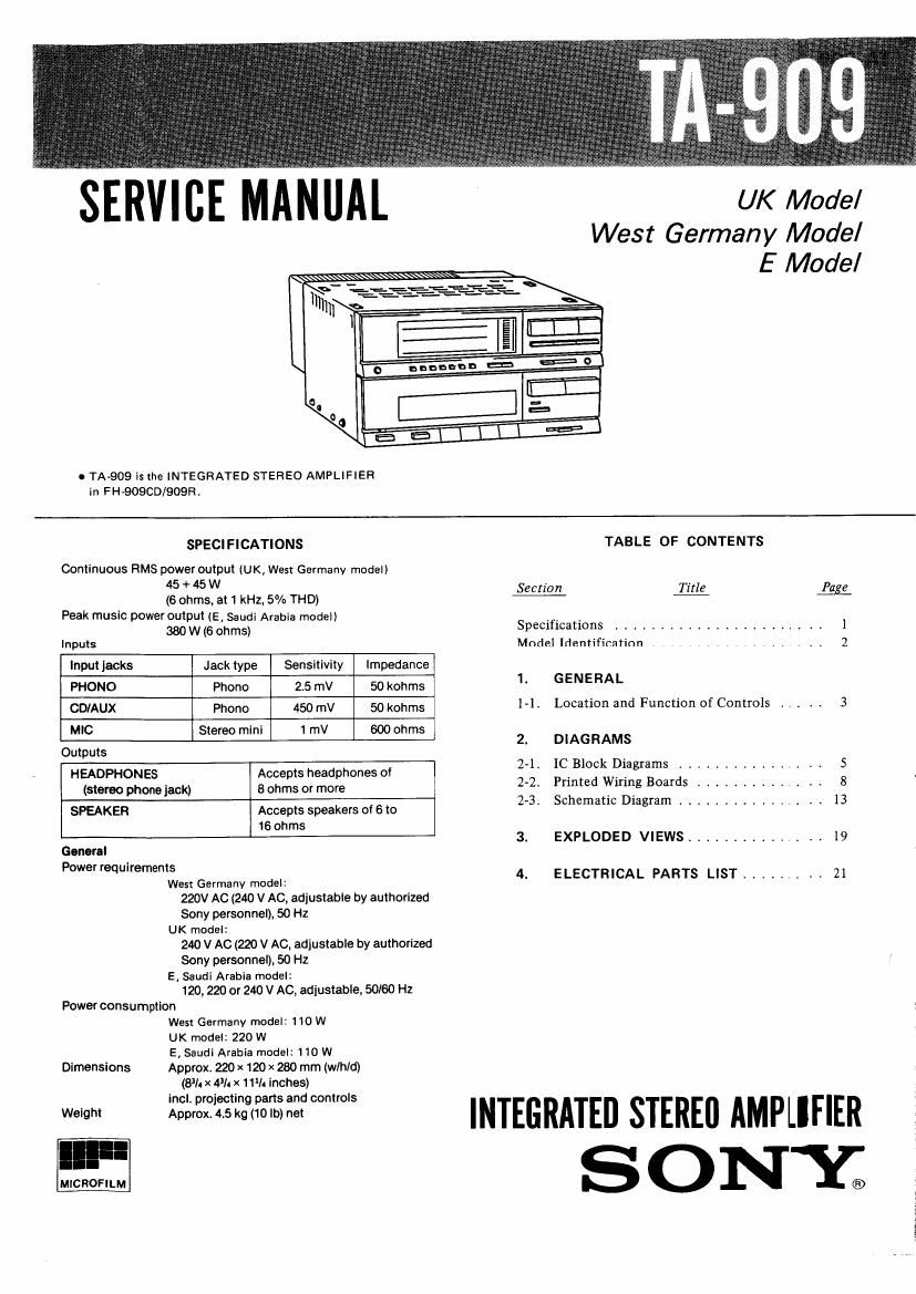
o TAA909 is the INTEGRATED STEREO AMPLIFIER
in FH-909CD/909R,
SPECIFICATIONS TABLE OF CONTENTS
Continuous HMS power output (UK, West Germany model)
45 + 45 w Section Titl Pug
(6 ohms, at 1 kHz, 5% THD) e 6
Peak music power output (E, Saudi Arabia model)
380 W (6 ohms) Specifications ...................... 1
Inputs Model Identification ................... 2
Input jacks Jack type Sensitivity Impedance
PHONO Phone 25 mV 50 kohms 1' GENERAL
CDIAUX Phone ,1me 50;)th lAlt Location and Function of Controls . I . t t 3
MIC Stereo mini 1 mV 600 ohms
2. DIAGRAMS
Outputs
HEADPHONES Accepts headphones of 2'1' 1931 Pfgmms """""""" 5
(stereo phone jack) 8 ohms or more 2-2, Printed Vilmng Boards .......... i I . 8
SPEAKER Accepts speakers of 6 to 23. Schematlc Dlagram ............ . , . 13
16 ohms
3. EXPLODED VIEWS ........... , t . 19
General
P°w°eq"°me"s 4. ELECTRICAL PARTS LIST ..... . . . 21
West Germany model:
220V AC (240 V AC, adiustabie by authorized
Sony personnel), 50 Hz
UK model:
240 V AC (220 V AC, adjustable by authorized
Sony personnel), 50 Hz
E. Saudi Arabia model:
120,220 or 240 V AC, adjustable, 50/60 Hz
Power consumption
West Germany model: 110 W
UK model: 220 W
E, Saudi Arabia model: 110 W
Dimensions Approx. 220 x 120 x 280 mm (w/h/d)
(81/4 X 43/4 x 11% Inches)
INTEGRATED STEREI] AMPLIFIER
I
'."' SON 'Y®
Page 2
TA-909
MODEL IDENTIFICATION
- Specification Label -
SONYe _MODEL N0. TA-9_09_
INTEGRATED STEREO AMPLIFIER
UK model: AC: 240 V ~ 50 Hz 220 W
- West Germany model: AC: 220 V ~ 50 Hz 110W
E, Saudi Arabia model: AC: 120/220/240 V ~ 50/60 Hz 110 W
SAFETY-RELATED COMPONENT WARNING
COMPONENTS IDENTIFIED BY MARK A 0R DOTTED
LINE WITH MARK A ON THE SCHEMATIC DIAGRAMS
AND IN THE PARTS LIST ARE CRITICAL TO SAFE
OPERATION. REPLACE THESE COMPONENTS WITH
SONY PARTS WHOSE PART NUMBERS APPEAR AS
SHOWN IN THIS MANUAL OR IN SUPPLEMENTS PUB-
LISHED BV SONY.