Pioneer ta 110 l service manual

This is the 11 pages manual for pioneer ta 110 l service manual.
Read or download the pdf for free. If you want to contribute, please upload pdfs to audioservicemanuals.wetransfer.com.

Page: 1 / 11
pioneer ta 110 l service manual

Extracted text from pioneer ta 110 l service manual (Ocr-read)


Page 1

CIRCUIT DESCRIPTIONS

REPAIR & ADJUSTMENTS

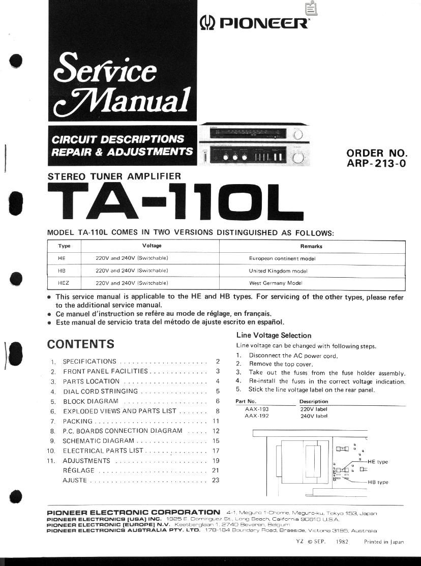
STEREO TUNER AMPLIFIER

(ID PIONEER;

ORDER NO.
ARP- 213-0

A-I'IOL

MODEL TA»110L COMES IN TWO VERSIONS DISTINGUISHED AS FOLLOWS:

Type Voltage

HE 220V and 240V lSwItchablel

HB 220V and 240V (Sw-tchablel
. HEZ 220V and 240V (Swnchablel

Remarks
European continent model
Unlted KIngdom model

WesI Germany Model

o This service manual is applicable to the HE and HB types. For servicing of the other types, please refer

to the additional service manual.

o Ce manuel dinstruction se refére au mode de réglage, en francais.
o Este manual de servicio trata del método de ajuste escrito en espafiol.

CONTENTS

SPECIFICATIONS .....................
FRONT PANEL FACILITIES ..............
PARTS LOCATION
DIAL CORD STRINGING ................
BLOCK DIAGRAM
EXPLODED VIEWS AND PARTS LIST .......
PACKING , . . .
PC. BOARDS CONNECTION DIAGRAM
SCHEMATIC DIAGRAM
ELECTRICAL PARTS LIST ...... _ .........
ADJUSTMENTS
REGLAGE ...........
AJUSTE .............

T'FSDWNRWEQNT

2
3

Line Voltage Selection

Line voltage can be changed wnh following steps,

1 Disconnect the AC power cord.

2 Remove the top cover.

3. Take out the fuses from the fuse holder assembly.
4 Re-install the fuses in the correct voltage indication.
5 Stick the line voltage label on the rear panel.

Part No. Descript-on
AAX7193 220V label
AAX»192 240V label

a

a
B an:

HE lvpe

iHB IVPE

PIONEER ELECTRONIC CORPORATION 4 'I Iwegwnv I mum Magma LII Trwym In: .Japari

PIONEER ELECTRONICS [USA] INC.
PIONEER ELECTRONIC [EUROPE] NLVL
PIONEER ELECTRONICS AUSTRALIA PTV. LTD.

I525 F m uunrwv C; I
Keetterglaa" I 2/40 Bavarian Hem .u
I78 can Runway , fined, Braesce v< Lama 31a: Aunrva a

I 'I'III PIC TI [:9 ICII'IIEI BDBWCJ LI EA

YZ © SI I. 198.7 Prmteu In Japan

Page 2

4. DIAL CORD STRINGING

. Remove the bonnet.
. Remove the tuning drum from the shaft of the
tuning capacitor.

3. Tie one end of the cord to the stud A located
inside the tuning drum.

4. Rotate the tuning capacitor right around until
the rotor blades are fully intermeshed.

5. Secure the tuning drum back onto the tuning
capacitor shaft, making sure that the securing
screw B faces directly upward.

6. Pass the cord out through the small opening in
the circumference of the tuning drum (see
diagram), and then take it over pulleys C and D
in that sequence.

7. Wind the cord around the tuning shaft 3 times.

8. Pass it over pulley E, wind it around the tuning
drum 2 times, and finally tie it to the spring

' hook F so that it is tensioned.

NH


Dial pointer

t.

Fig. 4-1

10.
11.

12.

13.

14.

TA-llDL

. Turn the tuning shaft, and check that the cord

moves smoothly.

Cut off any excess cord.

Turn the tuning shaft counter-clockwise
as far as it will go.

Align the dial pointer with the starting point
of the dial scale, and then pass the cord over
it.

Check that the dial pointer is in line with the
starting point of the dial scale.

Finally apply the locking paint to the cord
securing positions (stud A and spring hook F)
and the dial pointer connection.

Starting point

DFM lllllaalsol

STEREO TUNING Dial pointer

Tuning drum

Dial cord stringing