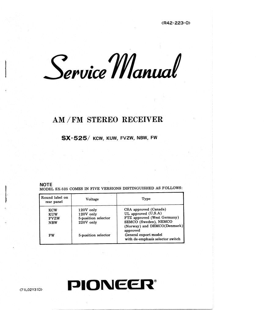
Pioneer sx 525 service manual
This is the 45 pages manual for pioneer sx 525 service manual.
Read or download the pdf for free. If you want to contribute, please upload pdfs to audioservicemanuals.wetransfer.com.
Extracted text from pioneer sx 525 service manual (Ocr-read)
Page 1
(R42- 223- 0)
firuice Manua/
AM / FM STEREO RECEIVER
SX-525/ ch, KUW, szw, NBW, FW
NOTE
MODEL SXv525 COMES IN FIVE VERSIONS DISTINGUISHED AS FOLLOWS:
Round label on
rear panel Voltage Type
KCW 120V only CSA approved (Canada)
KUW 120V only UL approved (USA)
FVZW 5~position selector FTZ approved (West Germany)
NBW 220V only SEMCO (Sweden), NEMCO
(Norway) and DEMCO(Denmark)
approved
FW 5-position selector General export model
with tie-emphasis selector switch
PIONEER®
Page 2
10.
SX-SEE
CONTENTS
SPECIFICATIONS ..................................... 3
FRONT PANEL FACILITIES ............................ 5
CONNECTION DIAGRAM ............................... 7
CIRCUIT DESCRIPTION
4-1 Block diagram ....................................... 9
4-2 Main amp unit ....................................... 11
DISASSEMBLY
5-1 Wooden case ....................................... 12
5-2 Frontpanel12
5-3 Bottom plate ....................................... 12
PARTS AND PCB LOCATION ,
6-1 Top View .......................................... 13
6-2 Bottom view ........................................ 13
6-3 Front View ......................................... 14
ALIGNMENT PROCEDURE
7-1 PM IF alignment .................................... 15
7-2 AM,IF alignment ................................... 15
7-3 FMtrackingaiignrnent......................, ........... 15
7-4 Checking of muting function ............................ 16
75 AM, tracking alignment ................................. 16
2-6 MPX decoder alignment ................................ 16
7-7 Checking the SCA filter ................................ 16
7-8 Checking the stereo indicator ............................. 17
DIAL CORD STRINGING ............................... 17
PACKING METHOD AND PART NUMBERS ............... 18
SCHEMATIC DIAGRAMS, PCB PATTERNS
AND PARTS LIST
10-1 Unit connection diagram and miscellaneous parts ............... 19
10-2 Tuner unit (AWE-003) ................................. K3