Pioneer sx 40 owners manual

This is the 7 pages manual for pioneer sx 40 owners manual.
Read or download the pdf for free. If you want to contribute, please upload pdfs to audioservicemanuals.wetransfer.com.

Page: 1 / 7
pioneer sx 40 owners manual

Extracted text from pioneer sx 40 owners manual (Ocr-read)


Page 1

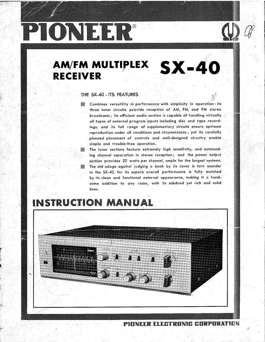
AM/FM MULTIPLEX _
RECEIVER sx 40

THE SX-4O - ITS FEATURES

Combines versatility in performance with simplicity in operation-its
three tuner circuits provide reception of AM, FM, and FM stereo
broadcasts; its efficient audio section is capable of, handling virtually
all types of external program inputs including disc and tape record-
ings; and its full range of supplementary circuits ensure optimum
reproduction under all conditions and circumstances; yet its carefully
planned placement of controls and well~designed circuitry enable
simple and trouble-free operation.

The tuner sections feature extremely high sensitivity, and-outstand-
ing channel separation in stereo reception; and the power output
section provides 20 watts per channel, ample for the largest systems.
The old adage against iudging a book by its cover is torn asunder
in the SX-40, for its superb overall performance is fully matched
by its clean and functional external appearance, making it a hand-
some addition to any room, with its subdued yet rich and solid

linest

INSTRUCTION MANUAL . r

Page 2

FUNCTIONS OF THE KNOBS AND SWITCHES ON THE FRONT PANEL

'1 :2 r}

4

5 6 7 8 0

1. STEREO INDICATOR LIGHT

With the SELECTOR switch set to the FM MPX
position, the stereo indicator light will go on when an
FM station transmitting an FM stereo broadcast is tuned
in. However, the stereo indicator light will not function
when the SELECTOR switch is set to any position other
than the FM MPX position.

2. DIAL SCALE - FM TUNER - THE POINTER
The pointer that is coupled to the TUNING control

(4) indicates the frequencies for FM broadcasts on the

upper section of the dial scaie. The FM tuner has a

tuning range of 88 to 108 megacycles.
3.- TUNING INDICATOR

The tuning indicator is a 'magic eye' type indicator '

for the FM and AM tuners, and it serves to indicate
the correct tuning point of broadcast transmissions as
stations are tuned in by manipulating the TUNING
control (4). The point where the shadowed portion
of the indicator closes down to a minimum for that
particular station is the tuning points (If the shadowed
portion does not close down very much, and there is
a lot of static in the reception, this is an indication
that the antenna input is inadequate. When using
only the built-in, ferrite loopstick antenna, try rotating
the antenna for improved reception. When using the

external lead antenna, extend the length of the lead
wire.l

14 15 , 6

4. TUNING

This is the tuning control for the FM and AM tuners.

5. BROAD/SHARP/AFC SWITCH

In AM reception, this switch serves as an lF band-
width selector. For quality broad bandwidth reception,
it should be set to the BROAD position (which provides
an IF bandwidth of i9kc.l, while for maximum selec-
tivity, it should be set to the SHARP. position (which
provides an IF bandwidth of i3'kc.l. I

In FM reception, it serves as the AFC defeat switch.
The station should first befituned in with the switch set
to the OFF position, and then the switch should be set
to the ON position. This ensures stable reception over
sustained periods of time without any station drift.

When a weak station on a channel adjacent, to a
much stronger station is being tuned in, the AFC switch
should be turned to the "OFF" position to prevent the

stronger station from pulling the tuning away from the;

desired weaker station.

6. FILTER . LOW

If there are marked 'rumble' noises emanating from
the turntable drive in disc record playback, or If there
is excessive noise in the low frequency ranges of the
record itself, this switch should be set to the ON

position. It provides 10 db of attenuation at 50 cps,
for noise-free reception.

7. FILTER - HIGH

If in playback of disc records there is excessive

crackling or hissing, this switch should be set to the;

ON position. It provides 15 db of attenuation at
10,000 cps, for enioyable reproduction. Also, if there
is excessive static in reception of radio broadcasts,
setting this switch to the ON position will alleviate the
noise to some extent.

8. TAPE MONITOR

This switch is of value when making recordings or
playing back recordings using 'a tape recorder. Please
refer to the paragraph on Using Tape Recorder With
SX-40' for details on its function. When this function
is not being used, this switch must always be set to
the NORM position,

9. MODE

This is the selector switch that provides selection of
modes of reproduction: stereophonic, monophonic or
Channel A and Channel B.

STEREO REV provides reversing of the channels

(when the left and right channel signals are to be

fed to the opposite speakers);

STEREO NORM provides normal stereophonic re-

production ;

MONO CH. A provides reproduction of signals of

Channel A only;

MONO CH. B provides reproduction of signals of

Channel B only; - »

MONO CH. A+B provides simultaneous reproduc-

tion of monophonic material over both channels.

10. POWER SWITCH

This is the AC power switch for the amplifier. It is
a pushebutton type switch.

11. DIAL SCALE - AM TUNER

The pointer that is coupled to the TUNING control i4i
indicates the frequencies for AM broadcasts on the lower
section of the dial scale.

'12. VOLUME - BALANCE

The outside control of the dual concentric knob is
the volume control for the amplifier. it is a coupled
control providing simultaneous control of both A and
B channels. _ , _

The inside control of the dual knob is the balance

control for the two channels. If thelef bhannel is too


low in volume level, this control shou e turned coun-
ter clockwise, while if,the right channel is too law,
then it should'be turned clockwise, to achieve the

correct balance.

13. LOUDNESS

One of the; characteristics of the human ear is, the
fact that at low volume levels, its sensitivity deteriorates
at high and low frequencies. The LOUDNESS control
is a low and high frequency, boosting control that is
incorporated to compensate for this characteristic.
When listening at low volume settings, this switch should
be set to the ON position for full frequency range

reproduction with depth and brilliance.

14, 15. TONE CONTROLS

The outside controls of the dual concentric knobs
are the bass controls, and the inside controls are the
treble controls. Control ll4l is for Channel A, and
Control (15) is for Channel 8.

The bass controls each provide +14 db of boost
to 713 db of attenuation at 50 cps, while the treble
controls each provide +11 db of boost to ~13 db

'of attenuation_at 10,000 cps.

16. SELECTOR

This is the input selector switch of the SX-40. It
provides selection of program source: disc records, or
radio broadcasts, and its positions are:

FM MPX For FM multiplex stereo

FM For FM broadcast reception

AM For AM broadcast reception
PHONO For disc record playback

AUX I Auxiliary input circuit for external

program sources.