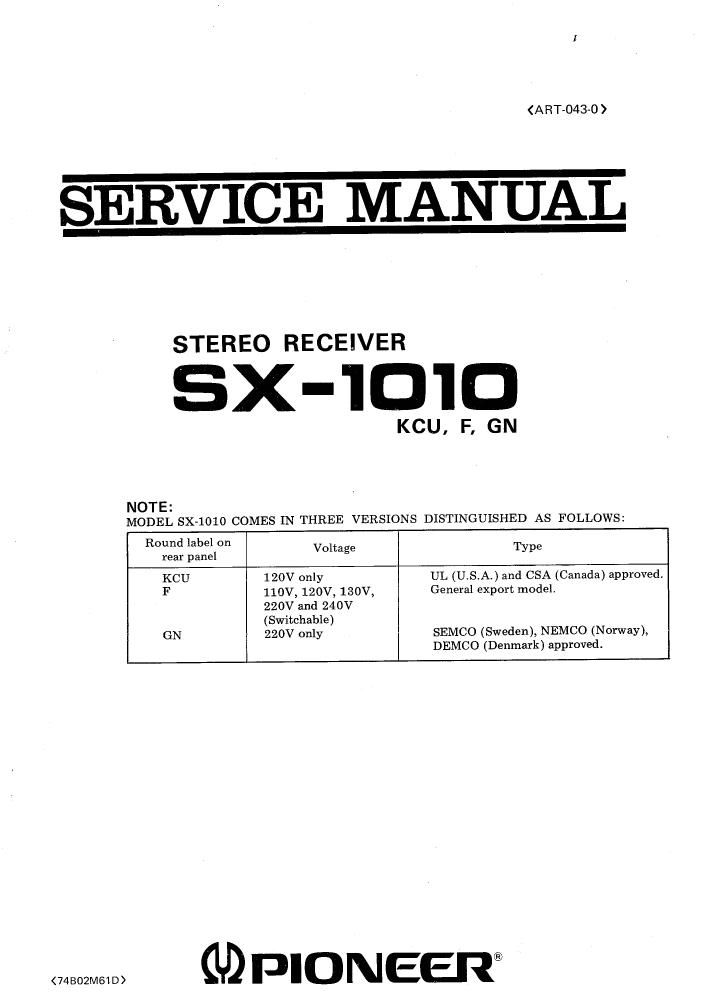
Pioneer sx 1010 service manual
This is the 71 pages manual for pioneer sx 1010 service manual.
Read or download the pdf for free. If you want to contribute, please upload pdfs to audioservicemanuals.wetransfer.com.
Extracted text from pioneer sx 1010 service manual (Ocr-read)
Page 1
8X- 1C10 CONTENTS About 220V only model labeled " GNu This model whose rear panel is labeled " GNu circular mark operates only on 220V substantially in its circuit design from two other models. When repairing this model please see the manual on page 75 and the followings which include such items as Circuit connection diagram , Miscellaneous parts list , Schematic diagram of power supply circuit assembly, P. C. board pattern and its parts list. Before servicing, also please do not fail to check to see if the " GN" mark is labeled on the rear panel. SPECIFICATIONS............................................... FRONT PANEL FACILITIES .................,.................... 5 CONNECTION DIAGRAM ..........................,............. 7 BLOCK DIAGRAM.......................................... .... CIRCUIT DESCRIPTION ......................................... DIAL CORD STRINGING..................................... .... DISASSEMBLY ................................................. PARTSANDP. BOARDLOCATIONS............................. 14 LEVEL DIAGRAM..................... ......................... ALIGNMENT PROCEDURE 10. 1 English................................................... 10. Abgleichverfahren .......................................... EXPLODEDVIEWANDPARTSUST............................... 20 SCHEMATIC DIAGRAMS , P. C. BOARD PATTERNS AND PARTS LIST 12. Circuit Connection Diagram and Miscellaneous Parts. . . . . . . . . . . . . .. 12. 2 FM Front End (AWB- 017).................................... 32 12. 3 Tuner Assembly (AWE- 040)................................... 33 12.4 Muting Circuit Assembly (AWM- O39)........................ .... 12. Equalizer Amplifier Assembly (AWF- 013) . . . . . . . . . . . . . . . . . . . . . . .. 12. 6 Control AmplifierAssembly(AWG- O27)..................... .... 12. 7 Power Amplifier Assembly (AWH- O32) .. . . . . . . . . . . . . . . . . . . . . . . .. 12. Protection Circuit Assembly (AWM- 062) . . . . . . . . . . . . . . . . . . . . . . . .. 12. 9 Power Supply Circuit Assembly (AWR- 053) .. . . . . . . . . . . . . . . . . . . .. 12. 10 Power Supply Circuit Assembly (AWR- O54) . . . . . . . . . . . . . . . . . . . . .. 12. 11 Switch Circuit Assembly (AWS-064) ............................ 12. 12 Switch Circuit Assembly (AWS-068) ............................ 12. 13 Switch Circuit Assembly (AWS- 069) ............................ 12. 14 Switch Circuit Assembly (AWS- 070) ............................ 12. 15 Switch Circuit Assembly (AWS-071) ............................ 12. 16 Switch Circuit Assembly (AWS- O72) ............................ 12. 17 5PConnectorAssembly(AWX- 062) ............................ PACKiNG METHOD AND PART NUMBERS .......................... 71 SCHEMATIC DiAGRAMS , P. C. BOARD PATTERNS AND PARTS LIST FOR 220V ONLY MODEL 14. 1 Circuit Connection Diagram and Miscellaneous Parts. . . . . . . . . . . . . . . \ .. 75 14. 2 Power Supply Circuit Assembly (AWR- 063) . . . . . . . . . . . . . . . . . . . . . .. 10. 11. 12. 13. 14.
Page 2
1 " SPECI FI CATIONS SEM!CONDUCTORS EETs ...................................................... 3 ICs ......................................................... 5 Transistors ............................................. 73 Diodes ................................................... 41 AMPLIFIER SECTION Continuous Power Output 20Hz~20kHz(Both channels driven) .................. WOW + 100W (8,Q), W5W + 105W (4,Q) 1kHz (Both channels driven) ......... 110W + 110W (S,Q), 110W + 110W (4,Q) Harmonic Distortion (20Hz~20kHz Continuous Power Output) .............................. Less than 0. (IW + 1W , Power Output) ............ Less than 0. 05% I ntermodulation Distortion (Continuous Power Output) ......... Less than 0. (IW + 1W , Power Output) ............ Less than 0. 05% Power Bandwidth (I H F , Both channels driven) ......... 5Hz~40kHz (T. D. 0.1%) Frequency Response ........................... 7Hz~100kHz I nput Sensitivity/I mpedance POVlfER AMP IN ........................... 1V/50k,Q Output Speaker ............................................. A , B , C, A + B , A + C, B + C (4,Q~16,Q) Headphone .................................... 4,Q~16,Q Damping Factor (1 kHz 8,Q) .................................... More than 50 Hum & Noise (IHF , short-circuited A Network) .................................... More than 100dB Residual Hum & Noise (S,Q , Pre & Power amplifier) ......... Less than 1 mV PR IEAMPLI FI E R SECTION Input Sensitivity/I mpedance PHONO 1 ....................................... 2. 5mV /50k,Q PHONO 2 ....................................... 2. 5mV/50k,Q PHONO Overload Level (rms/p- p) .................................."... MIC ................................................ AUX ................................................ TAPEPB1 ................................. TAPE PB 2 (D I N connector) ......... Output Level/I mpedance TAPEREC1 .............................. TAPE REC 2 (DIN connector) ...... PRE OUT ....................................... 250mV!700mV0mV /50k,Q 150mV/70kD 150m V /70k,Q 150mV!70k,Q 150mV 30m V /80k,Q 1V/1k,Q Harmonic Distortion (20Hz~20kHz) .............................. Less than 0.