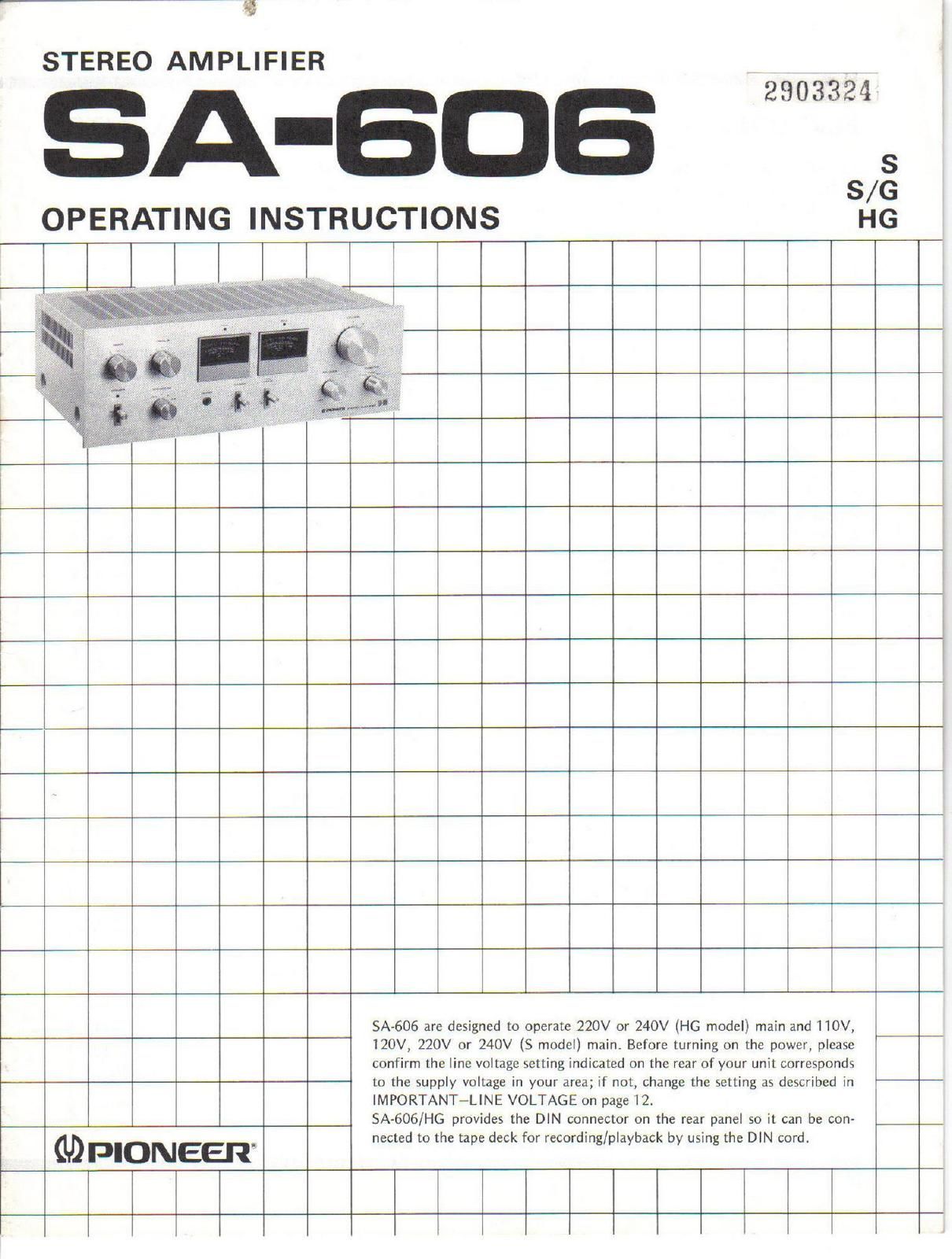
Pioneer sa 606 owners manual
This is the 18 pages manual for pioneer sa 606 owners manual.
Read or download the pdf for free. If you want to contribute, please upload pdfs to audioservicemanuals.wetransfer.com.
Extracted text from pioneer sa 606 owners manual (Ocr-read)
Page 1
3
STEREO AMPLIFIER
2903354
A .606
S
3/6
OPERATING INSTRUCTIONS HG
lllll
SA-606 are designed to operate 220V or 240V (HG model) main and 110V,
120V, 220V or 240V (S model) main. Before turning on the power, please
confirm the line voltage setting indicated on the rear of your unit corresponds
to the supply voltage in your area; if not, change the setting as described in
IMPORTANT-LINE VOLTAGE on page 12.
SA-606/HG provides the DIN connector on the rear panel so it can be con-
nected to the tape deck for recording/playback by using the DIN cord.
GDPIONEER
Page 2
FEATURES
Low-distortion, Stable-output Power Amplifier
The power amplifier stage adopts a high-reliability npn,
pnp silicon power transistor-based differential first-stage
current mirror load, all-stage direct-coupled pure comple-
mentary OCL circuit.
Continuous power output is 40watts* per chan-
nel, min., at 80th from 20Hertz to 20,000
Hertz with no. more than0.05%total harmonic
distortion.
This is an output which is more than sufficient for first-
rate reproduction of music so the SA-606 delivers a power-
ful and yet high-fidelity stereo reproduction for your enjoy-
ment. Moreover, the first-stage differential amplifier which
employs two power transistors and the constant current
circuit assures an stable operation stable even in the face of
fluctuations in the power supply voltage and external
temperature.
Equalizer Amplifier for the Faithful Reproduction
of Sound on Record
The equalizer amplifier adopts low-noise, high-gain IC
and it employs a dual positive and negative power supply
system for a maximum allowable phono input of lSOmV
(lkHz) with respect to a rating of 2.5mV. This means that
you can sit back and listen to practically distortion-free
record play when you use high-output cartridges or when
the music source is punctuated by high signal peaks. In
addition, the equalizer elements employ only those parts
that have undergone rigorous selection and deviation in the
20Hz~20kHz frequency band is kept down to 10.3dB.
These features ensure a reproduction of records which is
faithful to the original sound.
Power Meters that Allow the Output Level to be
Read Out Directly
The two large-sized meters located in the center of the
front panel incorporate logarithmic compression scales in
order to display the output level across a wide range from
0.01W to 100W. These handy meters mean that you can
directly read out the power level from 0.01! up to the
maximum output level of the SA-606 at an 8-ohm
impedance.
Two Sets of Speaker Systems can be Connected
The SA-606 comes with two sets of speaker terminal
and a speaker selector switch so you can compare the sound
through two different sets of speakers or place a second set
in another room. Another useful facility is the headphones
jack which allows you to listen to music in private late at
night through your stereo headphones.
Functionally Streamlined and Attractively
Designed Front Panel
The functionally designed front panel is made for easy
operation. Its two large-sized output meters in the center as
well as its knobs and switches which respond lightly to the
touch make operating the SA-606 a real pleasure.
The design matches that of other Pioneer hi- I stereo
components. Just one look is enough to reassure you that
you have bought the highest performance and most
attractively designed components available on the market.
* Measured pursuant to Federal Trade Commission s Trade Regulation rule on Power output Claims for Amplifiers.
Features ............................ 2
Stereo System Composition ............. 3
Installation Cautions .................. 3
Connection Diagram ................... 4
Connections ......................... 5
Front Panel Facilities .................. 6
Before Operation ..................... 7
Operation ........................... 7
CONTENTS
Using the Tape Decks .................. 8
Using the AUX Input Jacks ............. 9
Conditions Frequently Mistaken for
Malfunction ....................... 10
Specifications ........................ 11
Important-Line Voltage ............... 12
Schematic Diagram ............... Insertion