Pioneer SA 508 Owners Manual

This is the 12 pages manual for Pioneer SA 508 Owners Manual.
Read or download the pdf for free. If you want to contribute, please upload pdfs to audioservicemanuals.wetransfer.com.

Page: 1 / 12
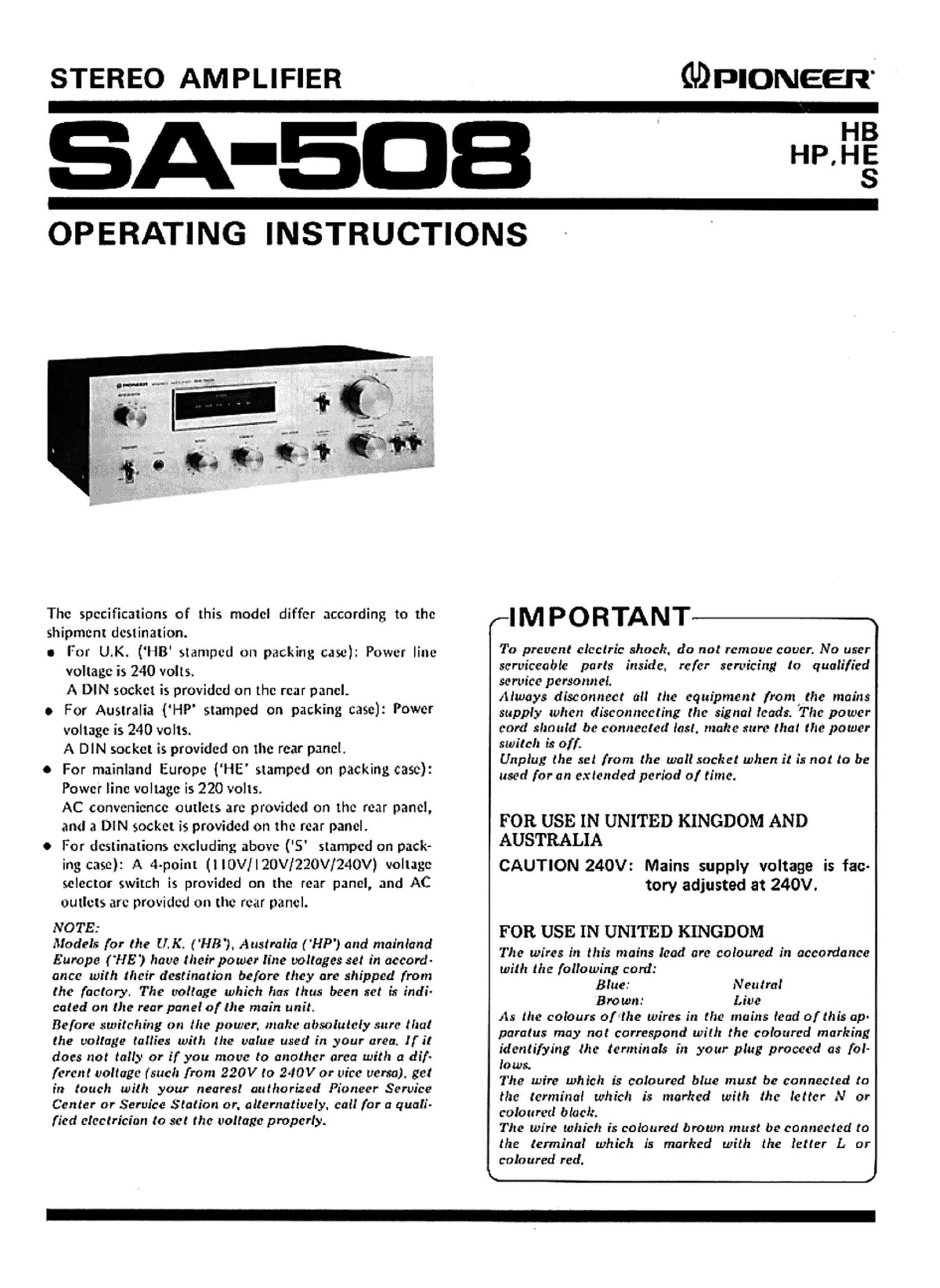
Pioneer SA 508 Owners Manual

Extracted text from Pioneer SA 508 Owners Manual (Ocr-read)


Page 1

STEREO AMPLIFIER

thlomeen'

A-SDB

HB
HP,HE
S

OPERATING INSTRUCTIONS

The specifications of this model differ according to the

shipment destination.

0 For UK. (llB' stamped on packing case): Power line
voltage is 240 volts.

A DIN socket is provided on the rear panel.

0 For Australia {HP stamped on packing case): Power
voltage is 240 volts.

A DIN socket is provided on the rear panel.

0 For mainland Europe {HE' stamped on packing case):
Power line voltage is 220 volts.

AC convenience outlets are provided on the rear panel,
and 3 DIN socket is provided on the rear panel.

0 For destinations excluding above ('5' stamped on pack-
ing case): A 4-point (llOV/I20V1220V/240V) voltage
selector switch is provided on the rear panel, and AC
outlets are provided on the rear panel.

NOTE:

Models for the U. K. ( HB'). Australia ( 'HP') and mainland
Europe (HE) have their power line voltages set in accord-
ance with their destination before they are shipped from
the factory. The voltage which has thus been set is indi-
cated on the rear panel of the main unit.

Before switching on the power, mahe absolutely sure that
the voltage tallies with the value used in year area, If it
does not tally or if you move to another area with a dif-
ferent voltage { such from 220V to 2401/ or vice verso). get
in touch with your nearest authorized Pioneer Service
Center or Service Station or. alternatively. call for a quali-
fied electrician to set the voltage properly.

r-IMPORTANT

To prevent electric shock. do not remove cover. No user
serviceable parts inside. refer servicing to qualified
service personnel.

Always disconnect all the equipment from the mains
supply when disconnecting the signal leads. The power
cord should be connected last. matte sure that the power
switch is off.

Unplug the set from the wall sachet when it is not to be
used for an extended period 0/ time.

FOR USE IN UNITED KINGDOM AND
AUSTRALIA

CAUTION 240V: Mains supply voltage is fac-
tory adjusted at 240V.

FOR USE IN UNITED KINGDOM

The wires in this mains lead are coloured in accordance
with the following cord:

Blue: Neutral

Brown: Live
As the colours orthe wires in the mains lead of this an
paratus may not correspond with the coloured marking
identifying the terminals in your plug proceed as fol-

lows.
The wire which is coloured blue must be connected to

the terminal which is marked with the letter N or

coloured black.
The wire which is coloured brown must be connected to

the terminal which is marked with the letter L or
coloured red.

\ J

Page 2

CONTENTS
Features ......... . .................. 2 Operations ................. . ........ 10
Stereo System Composition ............. 3 Using the Tape Decks ......... . ........ 11
Installation Precautions ................. 3 Conditions Frequently Mistaken for
Rear Panel Facilities ........ ' . ..... . . . 4 Malfunctions ....................... 12
Connections ......................... 5 Specifications ................... Insertion
Front Panel Facilities .................. 8 Schematic Diagram --------------- Insertion

FEATURES

Power Amplifier Section that Packs :1 Consistently
Stable Power Punch

The power amplifier section adopts a singlevstage differ-
ential amplifier with a current mirror load, all-stage direct-
coupled pure complementary OCL circuit. in particular, the
first stage has a differential amplifier circuit with dual tran-
sistors to keep down the fluctuations in the characteristics
such as temperature variations to bare minimum. A current
mirror load is featured in this differential amplifier circuit
which paves the way to a high amplification design. This
generates a high level of negative feedback and assures the

reproduction ofa Continuous Power Output of
25 watts per channel, min., at 80th
from 20 Hertz to 20,000 Hertz with no more
than 0.03 % total harmonic distortion.

Phono Circuitry with Plenty of Leeway in the SIN
and Other Characteristics

The low-noise transistors and low noise elements com-
bine to produce a signal-tonoise ratio (PHONO) of 76dB
(lHF-A). As a result, the RIAA deviation, which has a great
bearing on the sound quality, is improved to £0.5d8 (over
30 to 15,000Hz), and the phono overload level is I40mV
(lkHz, T.H.D. 0.1%) with respect to a 2.5mV rating. This
is, then, a design which has plenty to spare and which per.
mits the almost distortion-free play of records on your
turntable for the best in highftdelity.

Power Level Indicator with Fluorescent Display
Tubes

Use for the power level indicator are two fluorescent
display tubes (one for the left channel and the other for the
right) which feature a very fast response speed to indicate
the power level virtually instantaneously. This indicator is
composed of highly dependable le and its logarithmic
compression and drive circuits make it possible for a wide
range of power levels from 0.0 right up to the maximum
levels to be indicated for both the left and right channels in-
dependently without switching knobs or levers.

Rich Store of Accessory Functions

0 The subsonic filter switch serves to cut out the low-
frcqucncy noise, which is harmful to your speakers, ge-
nerated by record warp.

e The loudness switch compensates for the deficiencies of
the human ear with respect to low-frequency sound and
it is also useful when listening to programs at night, for
instance, with the sound turned down.

0 The function indicators tell you the program source at a
glance.

e The amplifier is provided with two sets (A and B) of
speaker terminals so that you can connect two sets of
speaker systems. This means that you can listen to the
program on one set in another room.

0 The amplifier is also equipped with two sets of tape deck
jacks for connecting two tape decks. The tape monitor
switches can be used to dub tapes from TAPE 1 deck to
TAPE 2 deck and for simple tape editing.

a ' Measured pursuant to Federal Trade Commission's Trade

Regulation rule on Power Output Claims for Amplifier.