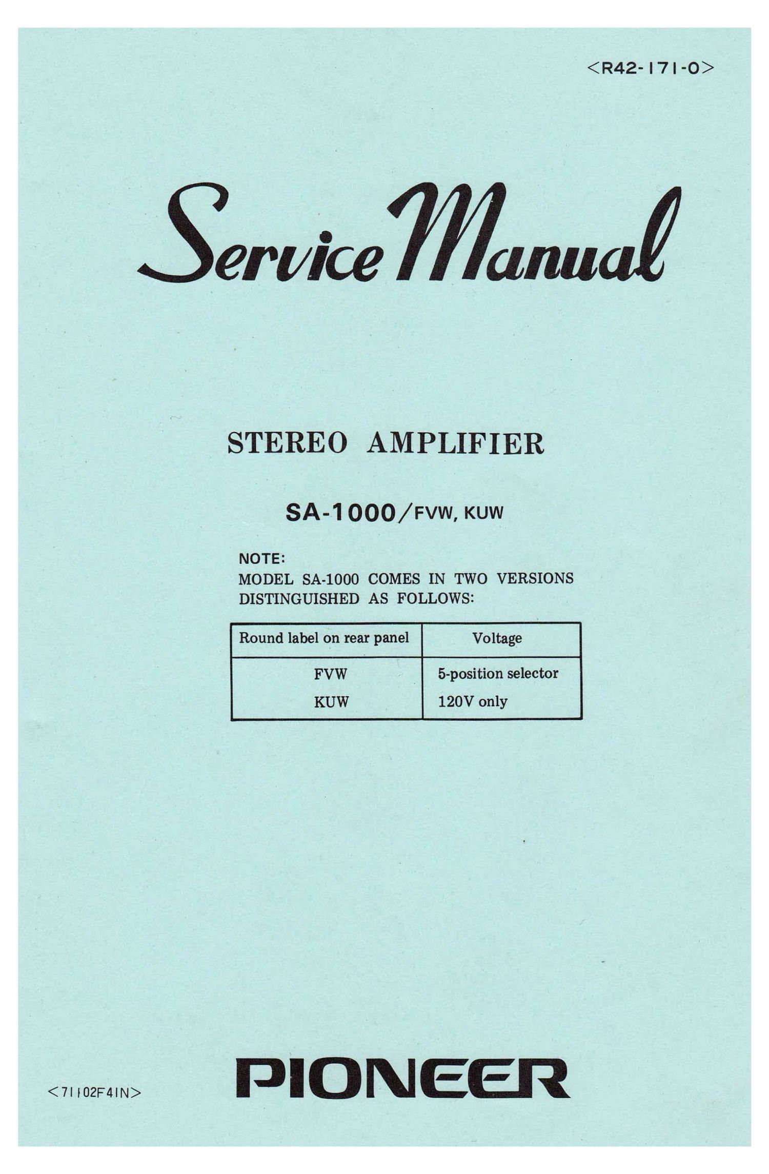
Pioneer SA 1000 Service Manual
This is the 40 pages manual for Pioneer SA 1000 Service Manual.
Read or download the pdf for free. If you want to contribute, please upload pdfs to audioservicemanuals.wetransfer.com.
Extracted text from Pioneer SA 1000 Service Manual (Ocr-read)
Page 1
erl/ice Mum
STEREO AMPLIFIER
SA-1000/FVW, KUW
NOTE:
MODEL SA-lOOO COMES IN TWO VERSIONS
DISTINGUISHED AS FOLLOWS:
Round label on rear panel Voltage
FVW ' 5-position selector
KUW 120V only
PIONEEI?
Page 2
SA-1 000
CONTENTS
SPECIFICATIONS ................................... 3
BLOCK DIAGRAM .................................. 5
2-1 Low level input circuit ............................... 7
2-2 Head amplifier .................................... 7
2-3 High level inputs and control circuits ..................... 7
2-4 Control amplifier ................................... 7
2-5 Filters .......................................... 7
2-6 Main amplifier ..................................... 7
2-7 Protector circuit ................................... 7
2-8 Power supply ..................................... 8
ANALYSIS OF SOME SELECTED CIRCUITS
3-1 Quasi-complementary push-pull output .................... 9
3-2 D.C.biasapplycircuit........................., ..... 10
3-3 Drive amplifier .................................... 11
3-4 D. C. neutral potential stabilizer ........................ 11
3-5 Signal negative feedback circuit ......................... 11
36 D. C. neutral voltage detector ......................... 11
3-7 Overload detector ................................... 12
DISASSEMBLY
4-1 Removal of the cover ................................ 13
4-2 Removal of the bottom plate .......................... 13
4-3 Removal of the front panel ............................ 13
4-4 Removal of the metal housing .......................... 13
4-5 Removal of the units ................................ 13
PERFORMANCE CHECKS AND ADJUSTMENTS
5-1 D. C. voltage check ................................. 14
52 D. C. neutral voltage & detector circuit adjustment ............ 16
5-3 Idle current adjustment .............................. 16
SCHEMATIC AND PRINTED CIRCUIT BOARDS
6-1 Unit connection diagram .............................. 17
6-2 Head amplifier unit ................... - .............. 19
63 Control amplifier unit ............................... 20
6-4 Filter unit ........................................ 21
65 Main amplifier unit ................................. 22
6-6 Protector unit ..................................... 24
6-7 Power supply unit .................................. 25
PARTS LIST
7-1 Miscellaneous parts ........................ , ......... 26
7-2 Head amplifier unit ................................. 29
7-3 Control amplifier unit ................................ 30
7-4 Filter unit ........................................ 31
7-5 Main amplifier unit .............................. ". . . 32