Pioneer siw 891 service manual

This is the 9 pages manual for pioneer siw 891 service manual.
Read or download the pdf for free. If you want to contribute, please upload pdfs to audioservicemanuals.wetransfer.com.

Page: 1 / 9
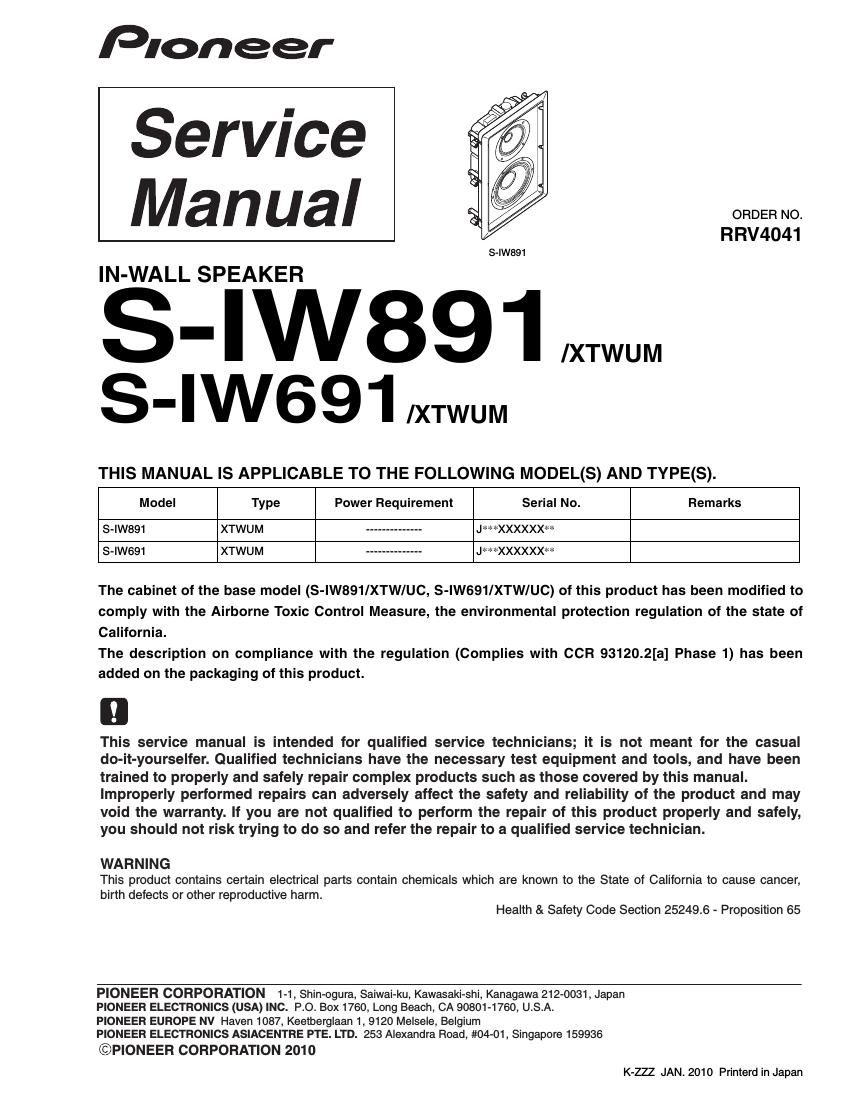
pioneer siw 891 service manual

Extracted text from pioneer siw 891 service manual (Ocr-read)


Page 1

2 S-IW891 1234 CD F A B E 1 23 4 1. REASSEMBLY AND DISASSEMBLY PRECAUTIONS - The grille is inserted into the baffle. To detach it, insert a grille removal tool into each of the 4 corner holes of the grille net and push up carefully. - The Speaker frame is attached to the wall by 6 external screws. To detach it, unfasten those screws. - The LPF network is attached to the speaker frame by 2 external screws. To detach it, first disconnect the cord to speaker. Next remove the frame. Then unfasten those screws and disconnect the cord to the HPF. - The HPF network is attached to the CST chamber inside of speaker frame by 5 screws. To detach it, first detach CST and disconnect the cord to speaker & LPF network. After removing the CST, disconnect the cords to the speakers and the connector to the Level Control Assy. After then, remove the baffle from the frame and disconnect the cord to WF. And then, unfasten 5 screws tightened to the HPF network. Caution ; When re-attaching the HPF network, apply DIABOND (black) (DB-1600WB) to the contact area to the wooden bar and the through hole for cord again. - The CST speaker is attached to the baffle by 4 external screws. To detach it, unfasten those screws and then, disconnect the wire connection. When reattaching it, face Mid terminal (bigger) rightward. - The woofers are attached to the baffle by 6 external screws. To detach them, unfasten those screws and then, disconnect the wire connection. When re-attaching them, face its terminal lower right. - At t a c h t h e s p e a k e r f r a m e t o t h e w a l l /c e i l i n g , a n d tighten the screws lightly (temporary attachment). At this point the rotating clamp will rotate so that the rotating clamp and frame are clamped on to the wall/ceiling. Gently try pulling the speaker forward and check that all of the rotating clamps have rotated outwards and are lightly clamping to the wall/ceiling. - Tighten the screws firmly using no more than the maximum torque specified. Allowable maximum torque: 1.0 N . m Screw Speaker frame Rotating clamp

Page 2

3 S-IW891 567 8 5 6 7 8 C D F A B E Speaker System 2. EXPLODED VIEWS AND PARTS LIST Parts marked by "NSP" are generally unavailable because they are not in our Master Spare Parts List. The mark found on some component parts indicates the importance of\ the safety factor of the part. Therefore, when replacing, be sure to use parts of identical designation. NOTES: 2.1 PACKING 1 Carton Spacer SHB1188 NSP 2 1..Accessories Set (for Manual) SME3892 2..Polyethylene Bag S2 SHL1295 2..Operating Instruction SRD1385 (En/Frca) NSP 2..Warranty Card SRY1048 3 1..Grille Ass'y SMG1912 NSP 2..Scrim SER1367 NSP 2..Punching Net SNC1213 4 Polyethylene Bag S7 (for Grille) SHL1393 5 Top Protector SHA2615 NSP 6 1..Accessories Set SME3856 (for Adhesive Tape) 2..Adhesive Tape SEH1134 2..Adhesive Tape SEH6026 2..Polyethylene Bag SHL1246 NSP 7 1..Accessories Set SME3858 (for Removal Tool) 2..Polyethylene Bag SHL1246 2..Grille Removal Tool SLH1096 8 Install Template SRK1036 9 Protection Sheet SHB1199 10 Paint Mask SHC1870 11 12 Bottom Protector SHA2616 13 Polyethylene Bag SX SHL1479 14 Packing Case (for S-IW891) SHG2858 (for S-IW691) SHG2857 NSP 15 Label Serial SRW1112 16 Caution Label SRN1017 PACKING Parts List Mark No. Description Part No.