Pioneer shf 10 service manual

This is the 2 pages manual for pioneer shf 10 service manual.
Read or download the pdf for free. If you want to contribute, please upload pdfs to audioservicemanuals.wetransfer.com.

Page: 1 / 2
pioneer shf 10 service manual

Extracted text from pioneer shf 10 service manual (Ocr-read)


Page 1

ervice
Manual

SPEAKER SYSTEM

S-HF10 E

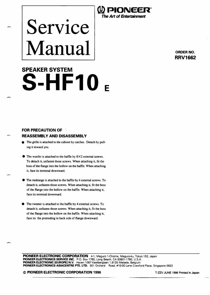
FOR PRECAUTION OF
REASSEMBLY AND DISASSEMBLY

. The grille is attached to the cabinet by catches. Detach by pull-
ing it toward you.

O The woofer is attached to the baffle by 8X2 external screws.
To detach it, unfasten those screws. When attaching it, fit the
boss of the flange into the hollow on the baffle. When attaching
it. face its terminal downward.

O The midi-ange is attached to the baffle by 4 external screws. To
detach it. unfasten those screws. When attaching it, fit the boss
of the flange into the hollow on the baffle. When attaching it.
face its terminal downward.

O The tweeter is attached to the baffle by 4 external screws. To
detach it, unfasten those screws When attaching it, fit the boss
of the flange into the hollow on the baffle When attaching it
face its the protruding in back side of flange downward.

GD PIONEERE

TheArtolEMerfinment

ORDER no.
RRV1662

PIONEER ELECTRONIC CORPORATION 4-1, Meguro 1-Chorna. Meguro-ku. Tokyo 153, Japan

PIONEER ELECTRONICS SERVICE INC. PO. Box 1760, Long Beach. CA 90801-1760, U.S.A.
PIONEER ELECTRONIC [EUROPE] N.V. Haven 1087 Keetberglaan 1,9120 Melsele. Belgium

PIONEER ELECTRONICS ASIACENTRE PTE. LTD. 501 Orchard Road. IMO-00 Lane Crawford Place. Singapore 0923

© PIONEER ELECTRONIC CORPORATION 1996

T-ZZV JUNE 1996 Printed in Japan

Page 2

S-HF10

PARTS LIST

NOTES:

0 Pam marked by "NSF are generally unavailable because they are not in our Master Spare Part: List.
0 The A'hrark found on some componentparrs indicates the importance afilie safety factor ofuie part. Therefore, when replacing,

be sure to useparts of identical designau'an.

O Pans marked by "©"are not always kept in stock. Their delivery time may be longer than usual or they may be unavailable.

For Packing
Mark No. Description Parts No. Mark No. Description Parts No.
Grille my SMG1503 Protector (for top) SHA1996
Network easy SWN1502 Protector (for bottom) SHA1998
Cosmetic packing SEB1206 Protection mat SS SHC1556
"iii."I terminal SKX1030 Packing case SHG1914
Speaker 20 (woofer) SWB1037
[Accessory set]
Speaker (iridrange) PWCCGO-SZF Speaker cord SDD-163
Speaker 26 (tweeter) FK26AP39-51 D Operating instructions saw 161
Screw (for woofer) SBA-133 (English/Spanish/Chines/Portuguese)
Screw (for midrange and tweeter) SBA1095
[Grille cosy]
Badge SAM1396
[Badge]
Badge SAM1393

SCHEMATIC DIAGRAM AND PARTS LIST

N ETWOR K ASSY (SWN1502)

Tweeter

Mark No. Description Parts No.
[Network assy]
C1 Capacitor (6.8uF) CES46R3KJ
CZ Capacitor (5.6uF) CES45H6KJ
03 Capacitor (1 .SuF) CESM FlSKJ
Poly switch $861008
L1 Choke coil (1 .2mH) STH1202
L2 Choke coil (0.56mH) STH1201
L3 Choker coil (0.39mH) STH1040

RSW has extreme positive resistance-temperature characteris-
tics. (Less mo. 39 orthonormal temperature). lfan abnor-
mal current flows to RS! due to an excessive input or unusual
Sinai. P.SW heats up and the resistance rapidly inueases. With
thisfunotion. thespcakersarcprutectedfromexoessiveinputor
unusual signal; The resistance value in awes even when using
a soldering iron for repairing. so allow it to cool More using.