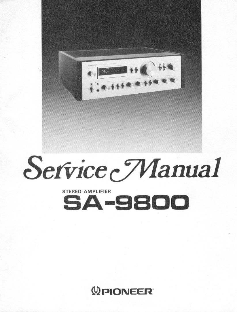
Pioneer sa 9800 service manual
This is the 54 pages manual for pioneer sa 9800 service manual.
Read or download the pdf for free. If you want to contribute, please upload pdfs to audioservicemanuals.wetransfer.com.
Extracted text from pioneer sa 9800 service manual (Ocr-read)
Page 2
MODEL SA-9800 COMES IN FIVE VERSIONS DISTINGUISHED AS FOLLOWS:
Type Voltage Remarks
KU 120V only U.S.A. model
KC 120V only Canada model
HG » 220V and 240V (Switchable) Europe or Oceania model
SIG 110V, 120V, 220V and 240V (Switchable) U.S. Military model
5 110V, 120V, 220V and 240V (Switchable) General export model
The variations in safety. standards in different countries has also necessitated variations in power supply and
circuit component specifications.
This service manual is applicable to the KU type. For the servicing of the other types please refer to the addi»
tional service manuals.
CONTENTS
1. SPECIFICATIONS ..................... 3 11.11 PA-R Assembly (GWH-120) ........... 45
2. FRONT PANEL FACILITIES .7 ............. 4 11.12 Tape Terminal Assembly (GWX-262) ..... 48
3. REAR PANEL FACILITIES ............... 7 11.13 Tape Switch Assembly (GWS-172) ....... 48
4. BLOCK DIAGRAM ..................... 8 11.14 Indicator Assembly (AWV-002) ......... 49
5. CIRCUIT DESCRIPTIONS 11.15 VR Assembly lGWX-256) ............. 51
5.1 Pre-amplifier Section ................ 8 11.16 Protection Assembly (AWMv163) ........ 52
5.2 Power Amplifier Section .............. 10 11.17 Rectifier Assembly (AWR-192) ......... 53
5.3 Indicator Circuit ................... 13 11.18 Power Supply Assembly (AWR-191) ...... 54
5.4 Protection Circuit .................. 14 Additional Service Manual for S, 3/6 Types ........ 57
6. DISASSEMBLY ....................... 15
7. PARTS LOCATION .................... 16
8. ADJUSTMENTS ....................... 18
9. PACKING ........................... 20
10. EXPLODED VIEW ..................... 21
11. SCHEMATIC DIAGRAMS, P.C. BOARD
PATTERNS AND PARTS LIST
11.1 Miscellanea ...................... 25
11.2 Schematic Diagram ................. 27
11.3 P.C. Boards Connection Diagram ........ 31
11.4 Input Terminal Assembly (GWX~261) ..... 35
11.5 CR Assembly (GWX-257) ............. 35
11.6 EO Assembly (GWF-116) ............. 36
11.7 Switch Assembly (GWS-171) ........... 39
11.8 TC Assembly (GWG-124) ............. 40
11.9 Filter Assembly (GWS~176) ............ 41
11.10 PA-L Assembly (GWH-119) ............ 42