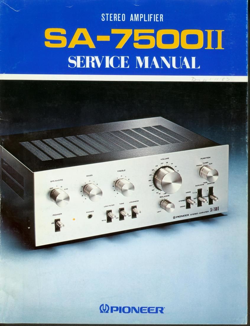
Pioneer sa 7500 mk2 service manual
This is the 38 pages manual for pioneer sa 7500 mk2 service manual.
Read or download the pdf for free. If you want to contribute, please upload pdfs to audioservicemanuals.wetransfer.com.
Extracted text from pioneer sa 7500 mk2 service manual (Ocr-read)
Page 2
SA-7EDOII
MODEL SA750011 COMES IN FOUR VERSIONS DISTINGUISHED AS FOLLOWS:
Type Voltage Remarks
7 , , 7 t7 , 77
KU 120V only I UL (U.S.A.I approved
1
KC 120V only CSA (CanadaI approved
7 7, .77 1 7 7
_ SEMKD (Sweden), NEMKO (Norway), DEMKO (DenmarkI
HG 220V and 240V (SwrtchableI and El (FInIand) approved
77, 777 777 , 7 7
S i 110V, 120V, 220V and 240V ISWItchabIeI General export modeI
This service manual is applicable to the KU-type, When repairing the KC»type, HG-type or S-type,
please see the additional service manual.
. CONTENTS
1. SPECIFICATIONS ..................................................... 2
. 2. FRONT PANEL FACILITIES ............................................ 3
3. CONNECTION DIAGRAM .............................................. 5
, 4. BLOCK DIAGRAM .................................................... 6
. 5. LEVEL DIAGRAM .................................................... 6
6. CIRCUIT DESCRIPTIONS
6.1 AF Section ....................................................... 7
6.2 Protection Circuit .................................................. 8
6.3 Power Supply Circuit ............................................... 9
7. DISASSEMBLY ....................................................... 10
a 8. PARTS LOCATION
8.1 Front Panel View .................................................. 12
8.2 Rear Panel View ................................................... 13
4 8.3 Front View with Panel Removed ...................................... 14
8.4 Top View ........................................................ 15
9. ADJUSTMENT ....................................................... 16
10. EXPLODED VIEW ..................................................... 17
11. SCH EIVIATIC DIAGRAMS, P.C. BOARD PATTERNS AND PARTS LIST
11.1 Miscellanea ....................................................... 24
11.2 Schematic Diagram ................................................. 25
11.3 Control Amplifier Assembly (AWG-047) ................................ 27
. 11.4 AF Amplifier Assembly (AWK-079) .................................... 30
12. PACKING ........................................................... 36