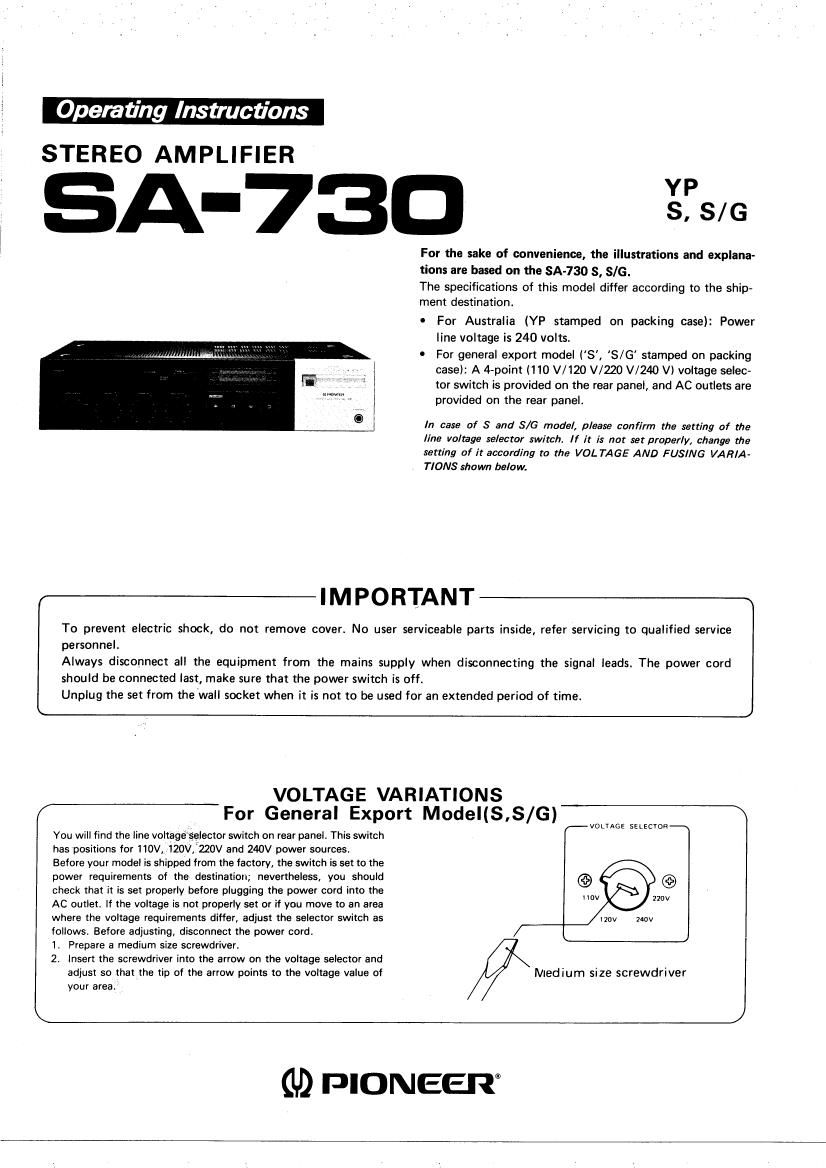
Pioneer sa 730 owners manual
This is the 6 pages manual for pioneer sa 730 owners manual.
Read or download the pdf for free. If you want to contribute, please upload pdfs to audioservicemanuals.wetransfer.com.
Extracted text from pioneer sa 730 owners manual (Ocr-read)
Page 1
Operating Instructions
STEREO AMPLIFIER
A-730 gas
For the sake of convenience, the illustrations and explana-
tions are based on the SA-730 S, 8/6.
The specifications of this model differ according to the ship-
ment destination.
- For Australia (YP stamped on packing case): Power
line voltage is 240 volts.
0 For general export model (8', S/G' stamped on packing
case): A 4-point 1110 V/120 V020 V/24O V) voltage selec-
tor switch is provided on the rear panel, and AC outlets are
provided on the rear panel.
In case of S and .576 model, please confirm the setting of the
line voltage selector switch. If it is not set properly, change the
setting of it according to the VOLTAGE AND FUSING VARIA-
TIONS shown below.
IMPORTANT
To prevent electric shock, do not remove cover. No user serviceable parts inside, refer servicing to qualified service
personnel.
Always disconnect all the equipment from the mains supply when disconnecting the signal leads. The power cord
should be connected last, make sure that the power switch is off.
Unplug the set from the wall socket when it is not to be used for an extended period of time.
VOLTAGE VARIATIONS
For General Export Model(S,S/G)
You will find the line voltage selector switch on rear panel. This switch
has positions for 110V, 120V,'220V and 240V power sources
Before your model is shipped from the factory, the switch is set to the
power requirements of the destination; nevertheless, you should
check that it is set properly before plugging the power cord into the
AC outlet. If the voltage is not properly set or if you move to an area
where the voltage requirements differ, adjust the selector switch as
follows. Before adjusting, disconnect the power cord.
1. Prepare a medium size screwdriver.
2. Insert the screwdriver into the arrow on the voltage selector and
adjust so that the tip of the arrow points to the voltage value of
your area.
voLr AGE SE Lscroe
Medium size screwdriver
(1,9 PIONEER
Page 2
i
l
REAR PANEL FACILITIES
(D TAPE 2/ADAPTOR ( I TERMINALS
Connect the recording (input) cords of a graphic equalizer or a
second tape deck to these terminals.
(23 TAPE 2/ADAPTOR ( I TERMINALS
Connect the playback (output) cords of a graphic equalizer or a
second tape deck to these terminals.
.13) GND TERMINAL
Connect the ground wire of the turntable to this terminal.
® PHONO TERMINALS
Connect the turntable's output cords to these terminals.
@ TUNER TERMINALS
Connect the tuner's output cords to these terminals.
© AUX/VIDEO TERMINALS
A television tuner or the audio output of a VTFt (Video Tape
Recorder) can be connected here, The terminals can also be used
as spare terminals for connecting other equipment,
® TAPE 1 (-I TERMINALS
The tape deck's recording (input) cords are connected hare.
TAPE 1 (-l TERMINALS
The tape decks playback (output) cards are connected here,
@ AUTO FUNCTION TERMINALS
The AUTO FUNCTION terminals are used when using the sA-730
with the Pioneer TX93O (TX-530), CT»730 (CT-930), PL-730 and
other similar components that are compatible with this function.
Connect each AUTO FUNCTION terminal on the $A-730 with the
corresponding AUTO FUNCTION terminal on each component.
Line Voltage Selector
PHONES TERMINALS
When this amplifier is housed in a Pioneer Stereo Rack, the
rack's headphones cord are plugged in here.
® SPEAKERS TERMINALS A
Connect the first pair of speakers to these terminals. When facing
the system in the listening position, connect the right speaker to
the R terminals and the left speaker to the L terminals.
® SPEAKERS TERMINALS B
Connect the second pair of speakers to these terminals.
63 POWER CORD
Plug into a household outlet (or the outlet of an audio timer)
NOTE:
If a humming noise should be heard during operation, first set the
power switch to OFF, and reverse the pin connections of the
power plugs on each of the components connected to the ampli-
fier and of the amp/ifiers power plug connected to the houshold
AC outlet and reconnect them to the power outlets,
@ Ac OUTLETS (SWITCHED)
Power supplied through these outlets is turned on and off by the
amplifier's POWER switch. Total electrical power comsumption of
connected appliances should not exceed 80W.
@ AC OUTLET (UNSWITCHED)
Power flows continually to this outlet, regardless of whether
amplifier is switched ON or OFF. Electrical power consumption
of the connected appliance should not exceed 100W.
NOTE:
Do not connect appliances with high power consumption such
as heaters, irons, or television sets to the AC OUTLETS. This can
cause the amplifier to malfunction.