Pioneer sa 620 schematic
This is the 3 pages manual for pioneer sa 620 schematic.
Read or download the pdf for free. If you want to contribute, please upload pdfs to audioservicemanuals.wetransfer.com.
Extracted text from pioneer sa 620 schematic (Ocr-read)
Page 1
GD PIONEER
Sefiice
Wanna]
REPAIR 8 ADJUSTMENTS I . ORDER NO.
7 ART- 640-0
STEREO AMPLIFIER _
A- B E 0
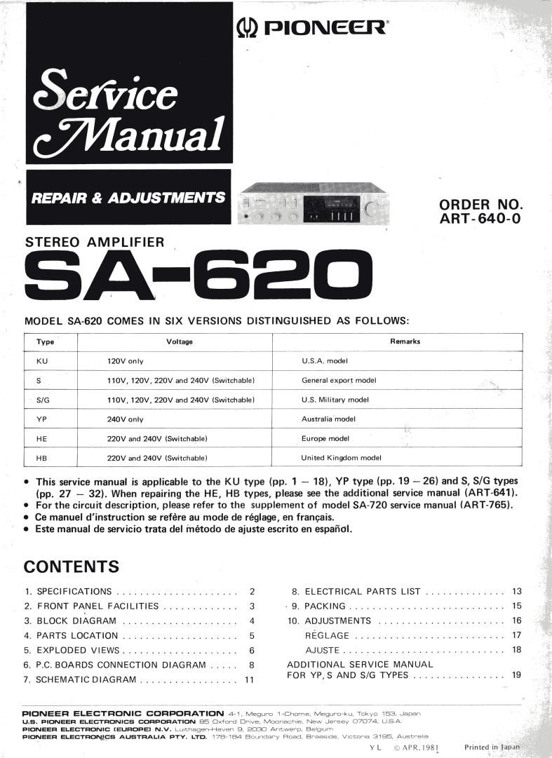
MODEL SA-620 COMES IN SIX VERSIONS DISTINGUISHED AS FOLLOWS:
W7 7 7-Voltage " -ne.;a3:7777 7 77
KU 120V only 777 7 U.S,A. model 7 77 l
l-iS 110V, 120V, 220V7 and 240V7 (Switchable) I General export model 74
5/6 7 110V, 1;C\I,:27;;nd 2407V7 (Switchable) V ill; Military model 7 7777
YP 7 240V only 7 l T Australia7;n707d7el 7 7 7 7
HE 220V and 240V (Switchable) l Europe 7rm7zv7d7e| -
H. ., M...;g§.g§..;,-i {7' .. 'Tf:
C This service manual is applicable to the KU type (pp. 1 - 18), YP type (pp. 19 - 26) and S, 8/6 types
(pp. 27 -- 32). When repairing the HE, HB types, please see the additional service manual (ART-641).
0 For the circuit description, please refer to the supplement of model SA-720 service manual (ART-765).
I Ce manuel dinstruction se refére au mode de réglage, en francais.
0 Este manual de servicio trata del método de ajuste escrito en espafiol.
CONTENTS
1. SPECIFICATIONS ..................... 2 8. ELECTRICAL PARTS LIST .............. 13
2. FRONT PANEL FACILITIES ............. 3 . 9, PACKING ........................... 15
3, BLOCK DIAGRAM .................... 4 10, ADJUSTMENTS ...................... 16
4. PARTS LOCATION .................... 5 REGLAGE .......................... 17
5. EXPLODED VIEWS .................... 6 AJUSTE ............................ 18
5. P.C. BOARDS CONNECTION DIAGRAM ..... 8 ADDITIONAL SERVICE MANUAL
7_ SCHEMATIC DIAGRAM IIIIIIIIIIIIIIIII 11 FOR YP, 8 AND S/G TYPES ................ 19
PIONEER ELECTRONIC CORPORATION 4 . .
U.5. PIONEER ELECTRONICS CORPORATION BE Ox3rd n-
PIONEER ELECTRONIC (EUROPE) N.v. -Jmagen» (mm 9
PIONEER ELECTRONICS Aus-rnALIA DTV. LTD. 475 84
.1 vuev u. 335 Ancr-am
Y L . \IR. i98l Printed in lawn