Pioneer qx 949 brochure

This is the 6 pages manual for pioneer qx 949 brochure.
Read or download the pdf for free. If you want to contribute, please upload pdfs to audioservicemanuals.wetransfer.com.

Page: 1 / 6
pioneer qx 949 brochure

Extracted text from pioneer qx 949 brochure (Ocr-read)


Page 1

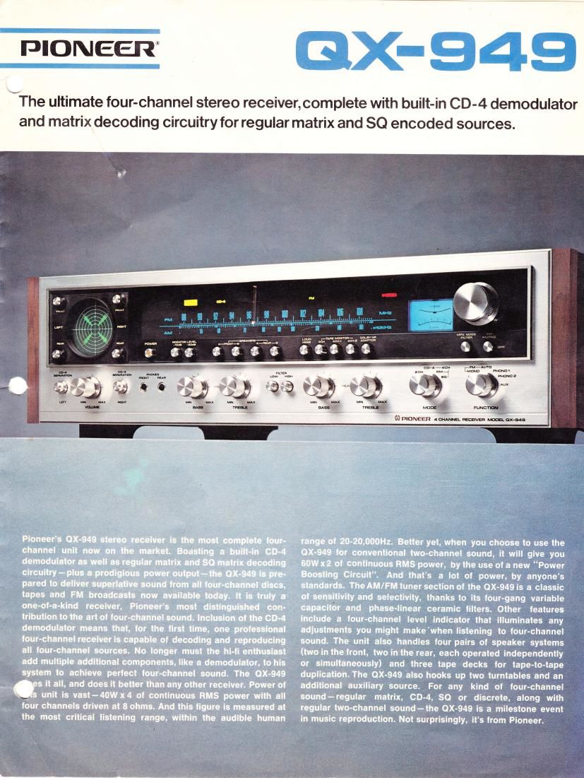
ffi.wffiffiffi ffi * $ t--T - i h$ * S -r$ * H $-$ tl.) [-]! L,i l",s Y {,} N Because the discrete four-channel disc (CD-4), unlike other matrix four-channel discs, employs a special modulation technique for engraving four-channel signal information onto one disc groove, a special demodulator is necessary to achieve perfect four-channel performance from these discs. The QX-949 has this special demodulator built-in. This de- modulator section employs an advanced circuit technology for stability and reliability, including PLL lC and FETs. lt is not an "extra" piece of equipment adding to the cost of your four-channel investment. Playing CD-4 records with the QX-949 is accomplished with ease. Clear sound localization, one of the major virtues of CD-4, is achieved bysimple mani- pulation of the separation controls and carrier level control by the use of the CD-4 test record that is included without cost with each receiver. These adjustments may be observed on the striking four-channel level indicator, another feature that is new and exclusive with the QX-949. Flfi$tJt,"dE$ iLtj!'ii'i.ri"!i , \i"Ii i i-": i 'i,'\'i i:.li{ i:.:i:,'i;r,r:i.-iItrl::i lj.i:li.r' rN The two other prominent four-channel systems for matrix decoding are also built-in to the QX-949- regular matrix and SQ matrix. This means that this new Pioneer receiver gives you a choice of all the important four-channel program sources, and has all the important four-channel circuitry built-in. The regular matrix position can be used to reproduce the majority of four-channel discs now available, and is equally effective in achieving excellent four-channel sound effects from your conventional two-channel discs or tapes. The SQ matrix posi- tion is used for ex- clusive playback of '., all SQ encoded pro- FSLu-' gram sources. {t} *tnSmgm FM S$&L"$C"&!_E AND Tirv{-} ,\ssyHR T#N*N* $YSTm&f} The FM dial scale of the QX-949 is the extra-wide linear type that facilitates easy and precise tuning of your favorite FM station. A frequency linear tuning capacitor employed in the FM front end of this receiver helps accomplish this task. ln addition, the QX-949 features the two-meter tuning system, one, a signal strength meter, the other, a center tuning type, which contributes immensely to precise tuning at all times. {?} fXW FH*NY mf\im W$Th{ FnstSS TYpN $:HTS Dual-gate MOS type FETs, distinguished by their low-noise characteristics, are used by Pioneer in the FM front end of the QX-949. They are applied to each RF and mixing stage. Coupled with the 4-gang variable capacitor used in this re- ceiver, these expensive and long-life solid state devices help contribute to an exceptionally high sensitivity ratio of '1.B,aV (tHf), as well as image rejection of more than BSdB and spurious rejection of more than 100dB. They ensure that you will receive all broadcast programs with great clarity, without jamming or irritating cross-modulation. {*} u**gL *$*K&-$-AYSW W*T',F{ ffi$-}f,T-*R il:in*{JiT The local oscillator section of the QX-949's FM tuner employs a buffer circuit to guarantee stable reception of weak broad- cast signals when powerful stations are situated near the weaker dnes. This circuit helps to suppress annoying cross- modulation as well as signal interruptions. {q} Namp.g-pKffis*ffin$.&N*H $*: isd TNffi sru$ $F sffisT$sh$ Highly advanced circuitry is characteristic of the QX-949's FM lF section. An exclusive LSI (Large-scaled lntegrated Circuit) is used in this section for supreme performance at all times. This new element is the performance equivalent of 203 more conventional elements, and thus ref lects the unusual attention to detail in manufacture given to the unit by Pioneer engineers. Additionally, the QX-949 features a quadrature detector in the unit's detector circuit that is distinguished both by excellent linearity and low-distortion characteristics over its wide frequency range. {S} pfi $ S N $R;$- $: *"i i \iIT Y * fl"{.i} F {: $: {""LFNT F N.&S$ t.i F.$W&N $T"Y Excellent phase linearity is assured over the wide signal bandwidth in the QX-949 by the use of new phase-linear ceramic filters employed in the FM lF section. These filters are also directly responsible for obtaining the high selectivity of more than 80dB (lHF) that is the minimum standard as- sured by this receiver. Even more than high sensitivity, the AndT/F[W $TH$*ffi* TilNWffi SffiST$SN

Page 2

selectivity figure gives evidence of the QX-949's FM tuning superiority in crowded FM station areas. (O} TUPX IC FOR EXCELLENT SEPARATION AND SCA BEAT *q- REJECTION Since the QX-949 employs a double-differential demodulation circuit, its stereo FM separation is very wide over the entire sound range- more than 40dB at 1KHz, and more than 30dB over the 50-1OKHz range. SCA beat is also suppressed. More- over, the low-pass filter utilized in the tuner section pos- sesses ultra-sharp characteristics so that carrier leakage is eliminated. {Z} OTNER TUNEH $HCTION FEATURFS The QX-949 is equipped with an FM muting switch that can- cels inter-station noise while you tune. lt also has a multiplex noise filter that eliminates FM stereo noise. The AM tuner section employs a 3-gang variable capacitor in the front end, along with a high-performance lC with excellent AGC charac- teristics, and ceramic filters in its lF section. This ensures exceptional AM sound quality. AMPLIFIER SECTION {1} DIHECT.COUPLED OCL POWER AMPLIFIER The power amplifier stage of the QX-949 is equipped with two separate DC power supplies and also features an all- stage direct coupled OCL circuit. The use of the direct- coupling design means that coupling capacitors are totally eliminated between individual stages; it also results in a super wide frequency response curve ranging from near DC to well beyond the audible sound range. The entire power bandwidth from 7 to 40,000H2 (8 ohms, H,D. 0.3%, four channels driven) is characterized by minimal distortion. And in terms of real power, the QX-949 is among the biggest four-channel re- ceivers on the market since it offers 40W x 4 of continuous RMS power(ZO-ZO,O0OHz, I ohms, four channels driven, har- monic distortion 0.3%). The 20-20,000H2 sound range, of course, is the most critical of all, since it is only within this range that the human ears are capable of hearing. lt is by far the best evaluation of a receiver or amplifier's true performance. {2} UhiIAUE PSWFR BOOSTING CIHCUIT When used in the four-chan- nel mode,the QX-949 delivers 40W x 4 of continuous RMS power. But when you choose to use it to play conventional two-channel sources, the unit's special "Power Boost- ing Circuit" converts this large four-channel power output to even greater two-channel power- up to 60W x 2 of continuous RMS power. This power conversion can be done by changing the 2CH/4 CH selector plug on the rear panel. This circuit device employs a micro power switch so that the conversion can be accomplished even when the amplifier's power is turned on. Additionally, this "Power Boosting Circuit" is not a BTL type; therefore it is free from the BTL circuit's drawbacks since the circuitry in the PBC is much less complicated than the typical BTL circuitry. The result is an extremely stable performance in either the two-channel or four-channel mode. This 60W x2 ot two-channel power also means that the QX-949 easily drives the front two pairs of speaker systems individually or simul- taneously. (S) NOVNNCED PROTECTION CIRCUIT The power amplifier section of the QX-949 includes an auto- matic protection circuit to protect your speakers and valuable power transistors from potential DC shock. This protection circuit also acts as a mut- i ing circuit to eliminate the irritating pop-noise that often occurs when you turn the power switch on. ilr,* (q) rOraL 40,000pF ELECTROLYTIC CAPACITORS The power supply section of the QX-949 employs large electrolytic capacitors to reproduce the extremely low-sound range with stability at high output power levels. These capacitors are the 10,000frF type selected for their extra power margin and for dynamic sound reproduction over the entire sound range. {5} TI.IREE-$TAGE DIRECT-COUPLED EQUALIZER Signals "clipped" at the equalizer stage are never again recovered even when they pass by the highest quality power amplifier. This signal loss leads to a stereo effect that is called "flat-topping". ln the QX-949, a three-stage direct- coupled equalizer circuit is employed with high DC voltage supply so that the phono overload level ratio is further im- proved. This equalizer design enables you to get the very finest sound from all two- or four-channel recordings and effective for eliminating clipping. (E} TCT.EQUIPPED NFts (NEGATIVE FFEDBACK} TYPE TONE CONTRO!. SECTION Bass and Treble tonal adjustment in the QX-949 may be inde- pendently applied to both front and rear channels. An FET (fietO Effect Transistor) is adopted in the top stage of this section to eliminate impedance variations. This solid state device also results in low-distortion characteristics when coupled with the NFB (Negative Feedback) type level charac- teristics. OTFIER DISTINCTIVE FEATURE$ I1 } FOUR.CI"IANNEL LEVEI- IIUDICATOR A unique four-channel level indicator is employed on the front panel of the QX-949 to permit you to observe the output level of each of the four channels appearing on the viewing screen. The level of each channel may be adjusted by using the level controls provided near the indicator. You will find the indi- cator to be valuable for all channel level adjustments. CD-4 separation adjustment, for example, is easily achieved by