Pioneer qx 949a owners manual

This is the 14 pages manual for pioneer qx 949a owners manual.
Read or download the pdf for free. If you want to contribute, please upload pdfs to audioservicemanuals.wetransfer.com.

Page: 1 / 14
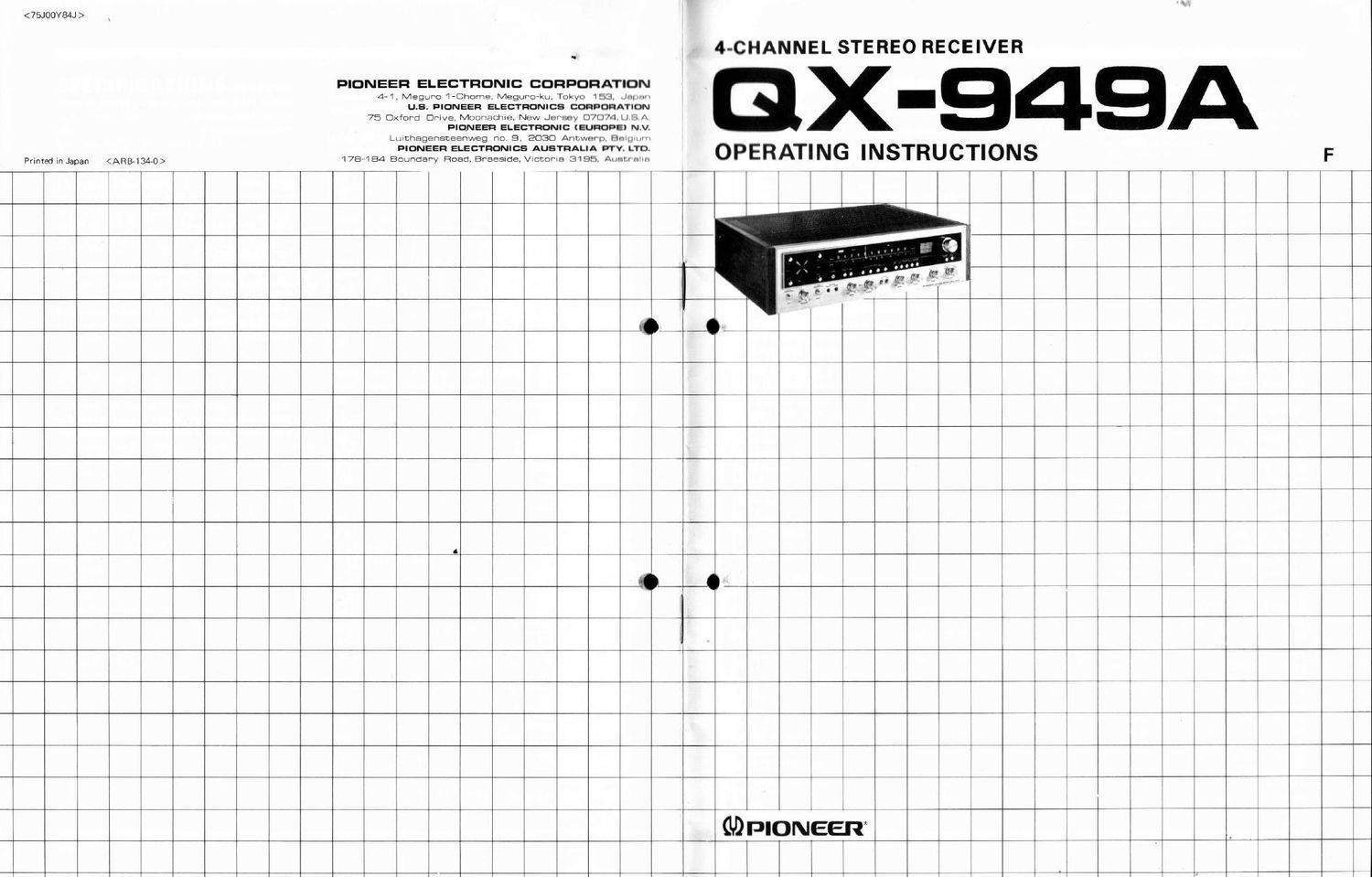
pioneer qx 949a owners manual

Extracted text from pioneer qx 949a owners manual (Ocr-read)


Page 2

Pioneer is sincerely grateful that you have selected the
QX-949A 4-channel Stereo Receiver. Wideflexibility has
been designed into this receiver to allow the enjoyment of
two and four channel sound in its many varieties. It is
compatible with all currently available program sources,
including discrete tape and CD-4 discs, RM and SO matrix
records and broadcasts, plus conventional two channel
media.

In order to realize the full performance and potentials of
this integrated receiver, we recommend that you read
this Operating Instructions thoroughly before attempting to
operate it.

INSTALLATION

Before connecting the QX-949A to speakers and

other components, determine its location in the

listening room. Please note that locations such as

the following could lead to deterioration of per-

formance or possible damage.

0 Direct sunlight, near radiators or other heat
sources

0 Places with poor ventilation, high humidity or
dust.

0 Locations which are not level, unstable or
subject to vibration

Do not use or keep volatile materials such as

insect sprays near equipment. Prepare a shelf or a

stand durable enough to support the QX-949A.

Due to the 45kHz frequency response required for
CD-4 reproduction, do not install the receiver near
equipment which may emit interference, such as
TV sets, etc.

ABOUT PROTECTION CIRCUIT

When the power of the QX-949A is turned on,
there is an approximately 3 seconds wait before
sound can be heard from the speakers. This is to
prevent surge currents from possibly damaging
transistors or speakers. If sound is not heard after
3 to 6 seconds, turn off the power and inspect
speaker connections.

During playing, if sounds stop or a continuous
relay switching sound develops, possible speaker
shorting is indicated. Turn off the power and
inspect speaker connections, wiring and speaker
impedance.

The protection circuit is self-resetting. After the
problem is rectified, normal playing can be re-
sumed.

E

CONTENTS

Installation ...................... 2
QX-949A Features ................ 3
4-channel System Composition ....... 4
Speaker System Installation ......... 5
Speaker Connection ...... : ........ 6
Antenna and Ground Connections 7
Turntable Connection .............. 8
AUX Input Terminals .............. 8
About 2CH Power Boosting Switch . . . . 8
Tape Deck Connection ............. 9
Connection Diagram ............... 10
Front Panel Facilities .............. 12
Before Playing .................... 14
FM and AM Broadcasts ............. 15
Playing CD-4 Records .............. 16
Playing 2-channel and Matrix Records, . . l7
Tape Deck Operation .............. 18
Employing DOLBYIINR ADAPTOR
Terminals ..... '. .................. 19
Using the AUX Terminals ........... 20
4CH MPX Output Terminal .......... 20
Line Voltage and Fuse ............. 20
Conditions Frequently Mistaken

for Malfunction ................... 21
CD-4 Technical Outline ............. 22
Matrix 4-channel Records ........... 23
Specifications .................... 24

*The word Dolbyis a trademark of Dolby

Laboratories Inc.

.9.

M

OX-949A FEATURES

Built-in CD-4 Demodulator

Discrete 4-channel CD-4 records, which possess outstanding
separation characteristics, can be played directly by simply
connecting a turntable equipped with a CD4 cartridge. The
built-in CD-4 demodulator is composed of ICs and provides
fascinating quadraphonic spaciousness.

RM & Full Logic SQ Matrix Decoders

Matrix encoded records and FM broadcasts are reproduced
with 4-channel concert hall realism, by built-in, regular
matrix (RM) and superior separation, IC, full logic, SQ
decoders.

Power Select Feature

Less output power per channel is required for comfortable
4-channel listening than for 2-channel operation. The power
select feature allows the user to choose between 4»channels
at 50W each or 2 channels at 75W each (with no more than
0.3% harmonic distortion at 4 ohms)

Power Amplifier

Four 10,000uF electrolytic capacitors are employed in the
low internal resistance power supply to yield an cxccp-
tionally wide power bandwidth. A|| stages of the high
output, low distortion amplifier utilize direct coupled
complementary OCL (output capacitorless) circuit. Output
throughout the range from 20Hz to 20kHz is 40W x 4
(with no more than 0.3% total harmonic distortion at 8
ohms).

Tone Control Amplifier

Individual tone controls are provided for both front and
rear channels. The transistorized negative feedback design
results in excellent signal-to-noise ratio with contour-less
variation characteristics.

Unique 4-channel Level Indicator

All four channel-output levels are simultaneously displayed
for easy one-glance comparison with a push button attenu-
ator system to adjust indicator sensitivity. This indicator
is especially convenient for the correct adjustment of CD-4
separation while using the test record supplied.

FM Front End with Dual-Gate FETs, Buffer Amp

The FM tuners sensitivity, overload resistance (ability to
receive very strong signals without distortion), image rejec-
tion and spurious rejection are determined chiefly by the
front end. State of the art components and circuit tech-
nology are incorporated into this receiver, including three
dual gate FET's, RF amplification, and buffer amplifier
between local oscillator and mixer stages. In all perform-
ance characteristics, the QX-949As FM tuner compares
favorably with the worlds most advanced specialized
tuners.

PIONEH?

Quadrature Detection, Phase Lock Loop (PLL)
Stereo Demodulator

Detection of the frequency-modulated signal is performed
by the quadrature" method with a balanced-bridge type
differential amp. This sophisticated design assures linearity
throughout the frequency band and reduces distortion to
the minimum. In the MPX circuit, a phase-lock-loop (PL L)
circuit design is used to give clear, stable separation atany
audio frequency. The circuit is equipped with an IC
(replacing six transistors) in a bridge configuration.

Comfortable FM Enjoyment

Unpleasant interrslation noise during FM station selection
is eliminated by the FM muting circuit, which operates
from the IF amplifier and FM detector voltage, to provide
truly comfortable listening. An FM multiplex noise filter
is also included to reduce noise during stereo broadcasts.

Advanced AM Circuitry

This section also incorporates integrated circuits and auto-
matic gain control in the RF and IF stages, as well as a
3-ganged variable capacitors for improved image ratio,
selectivity and lrequcncy response, plus reduced distortion.

Recorded Tape Duplication

Since connection terminals lor 2-channel and 4-channel
tape decks are provided together with a tape monitor
switch, users with two 4-channel tapc docks can duplicate
fourchannel recorded tapes, while those with a 2-channcl
and a 4-channel tape deck can record and edit in the desired
mode (CD-4, RM Matrix or SO Full Logic).

PERFORMANCE

The QX-949A is an integrated 4-channcl stereo receiver
which can operate with both conventional 2-channel and
4-channcl program sources. Functions in the 2-channcl
mode are: 2-channel stereo record playing, FM stereo
reception, AM reception, tape deck record and playback,
and auxiliary source.

The 4channel Functions of the QX-949A are:

i. 4-channel Discrete Reproduction
Four-channel record reproduction with CD-4 phono
cartridge equipped turntable; four-channel tape repro-
duction from 4-channel tape deck.

2. 4-channel Matrix Reproduction
Regular Matrix (RM) and SQ matrix record reproduc-
tion, FM matrix 4-channel broadcast reception.

3. Matrix Reproduction of 2-channcl Program Source.
RM or SQ matrix reproduciton can be performed with
2-channcl program sources such as stereo records, tape,
and FM stereo.

-