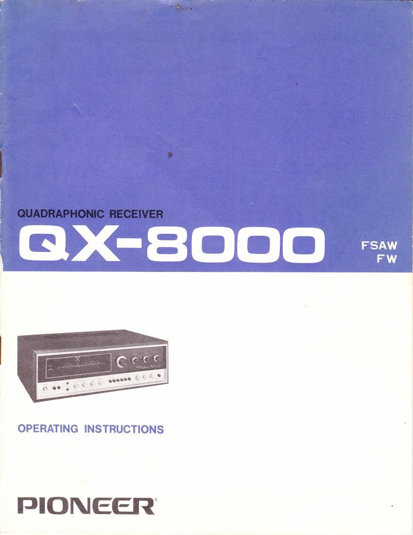
Pioneer qx 8000 owners manual
This is the 16 pages manual for pioneer qx 8000 owners manual.
Read or download the pdf for free. If you want to contribute, please upload pdfs to audioservicemanuals.wetransfer.com.
Extracted text from pioneer qx 8000 owners manual (Ocr-read)
Page 1
FEATURES FOUR.CHANNEL OUADRALIZER CREATES ,,ACOUSTICAL FIELD " The latest advance in sound realism: The exclusive Pioneer Ouadralizer creates an all-encompassing four- channel sound field, giving you the full, life-like sensation of being in an acoustically designed concert hall. CHOICE OF TWO OUADRALIZING EFFECT SYSTEMS The Ouadralizer creates 4-channel sound from any 2-channel stereo source (Tape, disk, FM). Moreover, it gives you a choice of two totally different 4-channel effects: ln "Matrix" operation, it builds up a room-enveloping sound field without specified instrument locations. Switched to "Phase Shift" operation, it produces normal, transparent two-channel stereo sound from the front speakers, and then adds a phase-shifted "wall of sound" with slight echo effect through the two rear speakers. An exclusive, original Pioneer development that preserves full stereo transparency while giving you that sensational life performance feeling. ALSO WORKS AS STANDARD 2-CHANNEL STEREO RECEIVER lf you only have one pair of speakers now, you can use the OX-8000 as a regular 2-channel stereo receiver and add the other two speakers at a later date. PERMITS 4-CHANNEL OR 2-CHANNEL TAPE RECORDING lf you already own a 2-channel stereo tape deck, you can go on using it for recording and playback as before. However, if you plan to buy a 4-channel tape recorder, you can use the Ouadralizer's full 4-channel capabilities, making your own "quadralized" tapes from 2-channel source material, and playing back 4-channel pre-recorded tapes with true 4- channel sound. FULLY EOUIPPED WITH 4.CHANNEL AUX. ILIARY CONTROLS AND INPUTS There are three balance controls: front left-right balance, rear left-right balance, and front-rear balance. These give you complete control over the quadralized sound field. Also. separate stereo headphones for the front and rear channels are provided-important when monitoring 4-channel tape recordings. Other features include "speakers in operation" indicator lamps, program indicator lamps, loudness switch, high and low filter switches, FM muting switch, 300S1 and 75O (coaxial) FM antenna terminals, and a 5- position channel mode selector. VERSATILE TAPE-TO-TAPE DUPLICATING FACILITIES 2-channel stereo tapes can be quadralized and dubbed onto a 4-channel tape deck (by using the preamplif ier outputs). Nor- mal 2-channel tape-to-tape dubbing is possible too, as well as 4-channel tape-to-tape dupl icating. CIRCUIT CONSTRUCTION rer.eoEIpPED FM TUNER The FM tuner is equipped with an FET in its front end to improve selectivity and sensitivity. Also, the lF stage employs one hybrid and one monolithic lC, replacing numerous transistors, ceramic filters, etc., and raising the tuner's sensitivity and selectivity. The FM MPX decoder works according to the time switching system and boasts ex- cellent channel separation. Tuning is made easy by the linear FM dial and the double (signal strength and center zero) tuning meters. BUILT.IN AM FERRITE BAR ANTENNA Sensitive and highly directional. An outdoor AM antenna is not required in most cases. LOW-D ISTORT ION, HIGH-POWER AUDIO AMPLI FI ER Both tone controls and equalization amplifier operate with a generous amount of negative feedback for improved fre- quency response accuracy and flatness. The power amplifier is a quasi-complementary design, a tried-and-true circuit construction. ALL NEW "OUADRALIZED" EXTERIOR DE- SIGN Cabinet and control panels are visual symbolizations of the Pioneer "Ouadralizer" concept, with a recessed, framed, square tuning dial, a modernistic and logically arranged control panel, and the famous silver-black-wood Pioneer color styling.
Page 2
LINE VOLTAGE AND FUSE CHANGING LINE VOLTAGE SETTING AND FUSE To remove the fuse, turn the fuse cap located on the line voltage selector in the direction indicated by the arrow. Then remove the fuse plug from the unit. Put the fuse plug back so that the proper line voltage marking can be seen through the cut in the edge of the plug. Whenever the position of the selector is changed, check the rating of the fuse. A 1.5-ampere fuse is to be used for either 220Y or 240V operation and a S-ampere fuse for 110V, 120V or 130V operation. if the rating of the fuse is correct, replace cap. FUSE REPLACEMENT If the fuse blows, remove the fuse with a new one. fuse cap and replace the TJIONEEFI Fig. 1 4-channel stereo system, the QX-8000, stereo receiver, can be combined with tape decks, turntables, etc. as shown in network (separately available Pioneer installed as shown in Fig. 2, a 2-way can be set up. CARTRIDGE TURNTABLE TAPE DECK TAPE PLAYER TURNTABLE TAPE DECK CARTRIDGETAPE PLAYER COMPOSITION A 4-CHANNEL STEREO SYSTEM To compose an ideal a solid state AM/FM four speaker systems, Fig. 1. If electronic crossover SF-500 or SF-700) is multiamplifier system PERFORMANCE OF QX.SOOO 4-CHANNEL STEREO PERFORMANCE With a 4-channel stereo tape deck or cadridge tape player installed, the QX-8000 can provide a 4-channel stereo playback of programs recorded on tape. 4-CHANNEL STEREO PERFORMANCE OBTAINABLE FROM A 2-CHANNEL STEREO SOURCE A 2-channel program source (a record, recorded tape, FM stereo program, etc.) can be reproduced in a high degree of a 4-channel stereo performance by either MATRIX system or PHASE SHIFT system through the provision of QUAD- RALIZER circuit in the QX-8000. For this 4-channel stereo performance, two speaker systems must be installed in the front and two speaker systems in the rear. For the QUADRALIZER circuit, see page 14. 2-CHANNEL STEREO PERFORMANCE A conventional 2-channel stereo performance can be provid- ed through an arrangement of two speaker systems in the front; left-side speaker system (CH. 1) and right-side speaker system (CH. 3). A 2-way multi-amplifier system can be set up by installing an electronic crossover network (see Fig. 2). SPEAKER SYSTEMS ELECTRONICCROSSOVERNETWORK (SF-7OO or SF-5OO) Fig. 2